4-5. STRINGHEAD INSTALLATION
1. Install gear collar (A) ensuring that collar spacer (B) is
in place (Figure 4-5A).
2. Insert holding pin (C) and thread stringhead onto shaft.
Tighten stringhead by hand only (Figures 4-5B and 4-
5C).
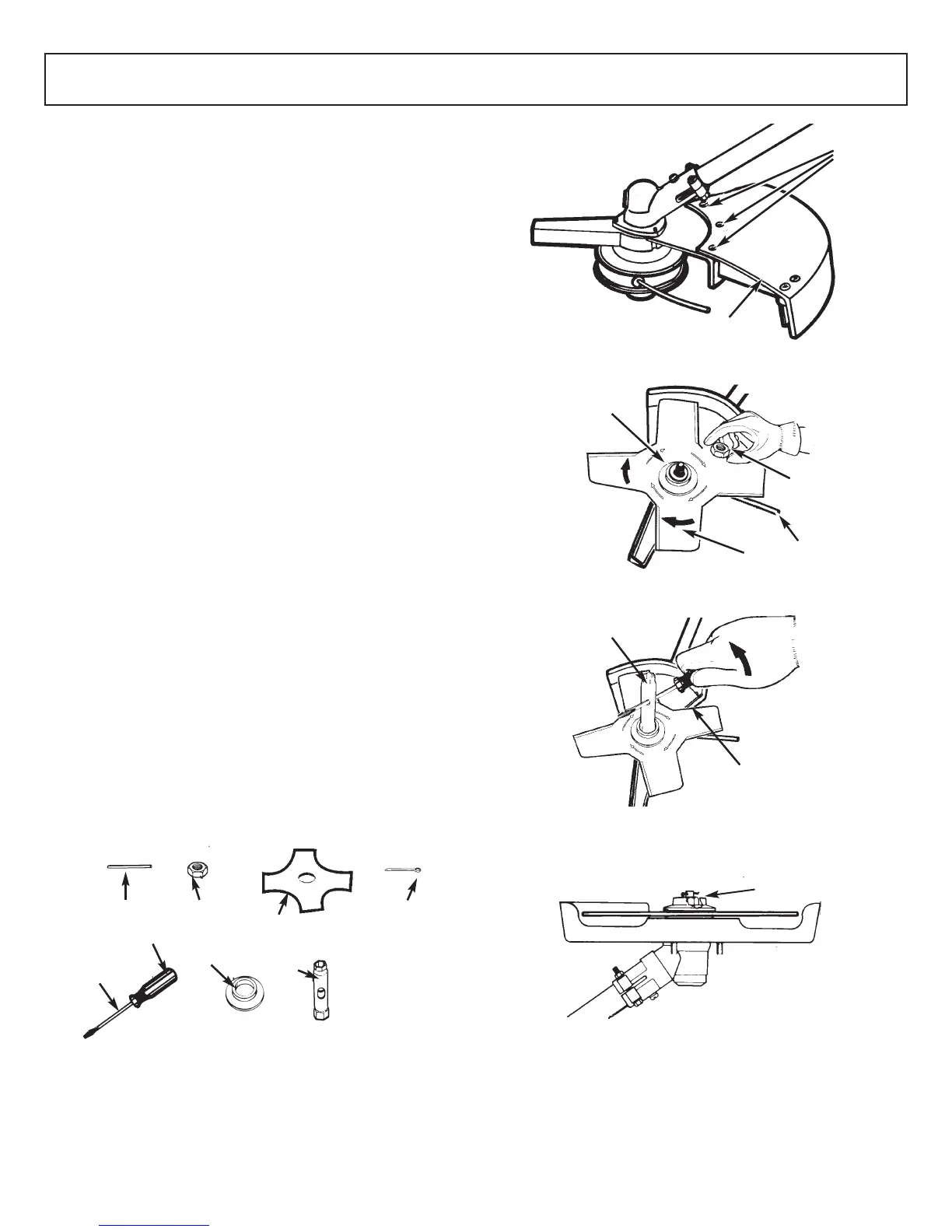
4-6. DEBRIS SHIELD INSTALLATION
(MT3090/MT30790)
1. Turn the unit over and with screws found in the hard-
ware bag install the debris shield (A) as shown (Figure
4-6A).
CAUTION
Debris shield must be installed to properly dispense cutter
line and protect operator.
REMINDER
Be sure to remove holding pin before starting unit.
87
4 - ASSEMBLY INSTRUCTIONS 4 - ASSEMBLY INSTRUCTIONS
4-7. BLADE INSTALLATION
(MT3090/MT30790)
WARNING / CAUTION
• NEVER use unit if blade is warped or has teeth that are
chipped or missing. Replace a damaged blade
immediately.
• NEVER operate unit with a blade unless metal blade
guard is properly installed. NEVER operate a unit with
a damaged guard.
• Always wear heavy-duty work gloves when handling
and installing a blade.
1. To install the blade you will need the items illustrated
above (screwdriver not provided): holding pin (B),
retaining nut (C), blade (D), screwdriver (E), flange (F),
socket wrench (G), cotter pin (H). (Figure 4-7A)
2. Remove three screws (J). Remove the shield (A). Insert
the holding pin into the gear collar slot to prevent the
collar from turning while removing the stringhead (turn
CLOCKWISE). (Figure 4-7B)
3. Leave the holding pin (B) in place. (Figure 4-7C)
WARNING
Be sure the blade center hole is properly sized to the collar
arbor.
4. Install blade (D) with teeth pointing CLOCKWISE as
shown in the illustration (Figure 4-7C).
5. Install flange (F) with FLAT SURFACE facing blade
(Figure 4-7C).
NOTE: Make sure blade is centered on collar arbor.
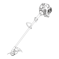
WARNING
6. Tighten nut (C) securely by turning it COUNTER-
CLOCKWISE with socket wrench (G). Remove holding
pin (Figure 4-7D).
7. Install cotter pin (H) (Figure 4-7E). Spread the ends of
the cotter pin apart to ensure retention.
4-5A
A
B
MT3075/
MT30775
B
MT3090/
MT30790
A
4-5B
MT3075/
MT30775
MT3090/
MT30790
C
C
4-5C
MT3075/
MT30775
MT3090/
MT30790
C
C
4-6A
A
MT3090/MT30790
4-7A
B
C
D
E
F
G
17mm
Supplied by
user
H
4-7B
A
J
4-7C
D
C
B
F
4-7D
C
G
4-7E
H