MUT E
OUT 1
OUT 2
Stan dby/O n/Re set
Button Common
3
2
1
+
-
84
B+
B-
U1:1
5
6
7
+
-
U1:2
3
1
2
Q5
10K
R58
22.1K
R51
ON Button +
100
R12
ON/RESET
LEFT PB AD
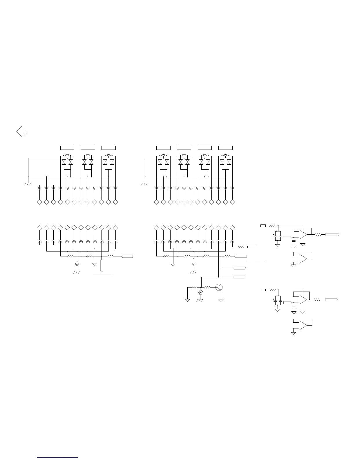
This Transister buffers the Standby button for the A/D matrix
10µF
C3
.1µF
C4
Vout LT
Vout LT
ADC-VREF-L
10K
R55
10K
R46
10K
R53
BYPASS
PRO C
TRIM
MH3
Chassis hole for Spark Ground
3.3V BU
Left Pushbutton A/D Buffer
To Right Pushbutton PCB
To Left Pushbutton PCB
SPARK GND-L
2
2
2
2
2
2
2
2
2
J2:1J2:5J2:3J2:4J2:6J2:2J2:10
J2:7J2:12J2:11J2:8J2:9
2
2
2
1A
1B
2A
2B
Spar k Gro und
Spar k Gro und
4A
3B
2
4B
Spar k Gro und
Spar k Gro und
Button Common
Vout RT
ADC-VREF-R
10K
R57
10K
R13
10K
R47
10K
R7
Chassis hole for Spark Ground
SPARK GND-R
2
2
2
2
2
2
2
2
2
J3:1J3:5J3:3
J3:4
J3:6J3:2
J3:10
J3:7J3:12J3:11
J3:8J3:9
2
2
2
1A
1B
2A
2B
Spar k Gro und
Spar k Gro und
4A
3B
2
4B
Spar k Gro und
Spar k Gro und
To Push&Hold reset circuit on Control PCB.
1A
.1µF
C50
MUTE OUT 1
Right Pushbutton PCB
2
2
2
2
2
2
2
2
S8S7S5 S6
2
J10:4
J10:5
J10:2
J10:1
J10:6
J10:3
J10:11
J10:7
J10:9
J10:10
J10:8
J10:12
2
2
2
1A
1B
2A
2B
Spar k Gro und
Spar k Gro und
SG12
SG11
SG10
SG9
4A
3B
2
4B
SG14
SG13
SG16
SG15
OUT 2 STANDBY
Spar k Gro und
Spar k Gro und
PB SPARK GND-R
Also connects to switch tab ground.
This Ground connects to the Chassis.
PROC
Left Pushbutton PCB
2
2
2
2
2
2
2
2
S4S3S2
2
J6:4
J6:5
J6:2 J6:1 J6:6 J6:3
J6:11
J6:7
J6:9 J6:10
J6:8
J6:12
2
2
2
1A
1B
2A
2B
Spar k Gro und
Spar k Gro und
SG4
SG3
4A
3B
2
4B
SG6
SG5
SG8
SG7
TONE BYPASS TRIM
Spar k Gro und
Spar k Gro und
PB SPARK GND-L
Also connects to switch tab ground.
This Ground connects to the Chassis.
3
2
1
+
-
8
4
B+
B-
U3:1
5
6
7
+
-
U3:2
RIGHT PB AD
10µF
C58
.1µF
C57
Vout RT
3.3V
Right Pushbutton A/D Buffer
.1µF
C55
3.3V
22.1
R65
D1
SPARK GND-R
22.1
R64
MH10
153462107121189
15 34 62 107
12
11 89 15 34 62 107
12
11 89
153462107121189
22.1
R66
22.1
R67
0V = Standby/On
1.6V = Out2
2.2V = Out1
2.5V = Mute
0V = Trim
1.6V = Bypass
2.2V = Proc
3.3V = Open
2.5V = Not used
3.3V = Open
Vout RT Levels
Vout LT Levels
 Loading...