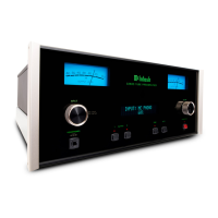
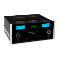
C 29 PERFORMANCE LIMITS
PERFORMANCE LIMITS
Performance limits are the maximum deviation from perfection
permitted for a McIntosh
instrument.
We promise you that when
you purchase a new C 29 from a McIntosh
Franchised
dealer it
will be capable of performance at or exceeding these
limits
or
you can return the unit and get your money back. McIntosh is
the only manufacturer that makes this statement.
PERFORMANCE
FREQUENCY
RESPONSE
+ 0 - 0.5 dB 20 Hz to
20,000
Hz
DISTORTION
.02% maximum at rated output level, 20 Hz to 20,000 Hz
INPUT SENSITIVITY AND IMPEDANCE
Auxiliary, TUNER, TAPE 1, TAPE 2, 0.25 volts at 100,000 ohms;
PHono 1 and PHono 2, 2 millivolts (1,000 Hz) at 47,000 ohms and 65
pF; Microphone, 2.5 millivolts at 10,000 ohms
HUM AND NOISE
Auxiliary, TUNER, TAPE 1, TAPE 2,
IHFA
100 dB, unweighted 90 dB
below rated output; PHono 1, PHono 2
IHFA
90
dB, unweighted
80
dB
below 10 millivolts input, equivalent to less than 1.0 microvolt at the
input terminals; Microphone, 1.5 microvolts at the input
terminals.
OUTPUT LEVEL AND IMPEDANCE
MAIN: 2.5 volts
with
rated input, less than 100 ohms source im-
pedance, to operate into 10,000 ohms or greater
TAPE: 0.25 volts with rated input, less than 200 ohms source im-
pedance, to operate into 10,000 ohms or greater
HEADPHONE/LINE:
0.75 volts into 8 ohm load or 2.5 volts into 600
ohm line, 47 ohm source inpedance, level
controls
provided
VOLTAGE AMPLIFICATION IN DECIBELS
Auxiliary, TUNER, TAPE 1 and TAPE 2
to MAIN Output
20
dB
to
TAPE Output
OdB
to HEADPHONE/LINE Output 30 dB
PHono 1 and PHono 2 at 1 kHz
to MAIN Output 62 dB
to TAPE Output 42 dB
to HEADPHONE/LINE Output 72 dB
MICrophone
to MAIN Output 60 dB
to TAPE Output 40 dB
to HEADPHONE/LINE Output 70 dB
GENERAL INFORMATION
SEMICONDUCTOR COMPLEMENT
9 Integrated Circuits
2 Transistors
11 Silicon Diodes
8 Light Emitting Diodes (LED)
1 Silicon
Controlled
Rectifier (SCR)
1 Dual Light Dependent Resistor Network (LDR)
POWER REQUIREMENT
120 volts, 50/60 Hz, 45 watts
FACILITIES AND FEATURES
BASS
CONTROLS
Separate 11 position rotary switches for each channel, +20 dB
to
-20
dB
at
20 Hz
TREBLE CONTROLS
Separate 11 position rotary switches for each channel,
+18
dB to
-18
dB
at 20,000 Hz
BALANCE CONTROL
Natural balance at center position, attenuation of left or right chan-
nel by rotating control
PRECISE TRACKING VOLUME CONTROL
A precision step volume control with left to right tracking accuracy
within 1 dB through its entire range.
SIX SOURCE INPUT SELECTOR
Auxiliary 1 and 2, TUNER, PHono 1 and 2, MICrophone
MODE SELECTOR
Seven positions: Left channel only to both speakers, Right channel
only to both speakers, Stereo Reverse, Stereo, Mono, L + R to left
speaker only, and L + R to right speaker only
TAPE MONITOR SWITCHES
Two pushbutton switches. Either of two tape recorders can be
monitored by selecting the TAPE 1 pushbutton or TAPE 2
pushbut-
ton. They are mechanically interlocked to accept only one pushbut-
ton at the IN position at one time.
TAPE COPY SWITCHES
Two pushbutton switches. Either of two tape recorders can be con-
nected to copy from tape recorder 1 to tape recorder 2 or vice versa.
They are mechanically interlocked to accept only one pushbutton at
the IN position at one time.
LF
-
HF FILTERS
Reduce unwanted high frequency noise (above 7 kHz) and low
fre-
quency rumble etc. (below 50
Hz)
at 12 dB per octave rate.
FRONT PANEL TAPE JACKS
Allows connection to input and output of a tape recorder from the
front panel. Inserting plugs into the front panel jacks disconnects
the TAPE 2 circuits from the rear panel and uses the TAPE 2 facilities
for the front panel jacks.
HEADPHONE JACK
For listening with either low or high impedance dynamic stereo
head-
phones. Power to this jack is supplied by an amplifier in the C 29.
Headphone listening can be
accomplished
without the use of an ex-
ternal power amplifier.
SPEAKER SWITCHES
(Operates with accessory speaker control relay) Turn Two sets of
speakers on or off when properly interconnected
with
the accessory
speaker control relay (the McIntosh
SCR
2).
MAIN
OUTPUT LEVEL
CONTRpLS
Permits the balance of the entire system to be conveniently preset.
HEADPHONE & LINE OUTPUT LEVEL CONTROLS
Adjusts the level and balance of the HEADPHONE/LINE output.
MECHANICAL INFORMATION
SIZE
Front Panel measures 16 inches wide (40.6 cm) by 5 7/16 inches high
(13.8 cm). Chassis measures 14 3/4 inches wide (37.5 cm) by 4 13/16
inches high (12.2 cm) by 13 inches deep (33.0 cm), including PANLOC
shelf
and back panel connectors. Knob clearance required is 1 1/4
in-
ches (3.2 cm) in front of the mounting panel.
FINISH
Front panel is
anpdized
gold and black with special gold/teal
nomenclature illumination. Chassis is black.
MOUNTING
Exclusive McIntosh developed professional PANLOC
WEIGHT
19 pounds (8.6 kg) net, 31 pounds (14.1 kg) in shipping carton
The continuous improvement of its products is the policy of
McIntosh Laboratory Incorporated, who reserves the right to improve
design without notice.
FRANCHISED DEALER:
MCINTOSH LABORATORY INC.
2 CHAMBERS
ST.,
BINGHAMTON, N.Y. 13903
607-723-3512
039138
Printed
m
U.S.A
 Loading...