11
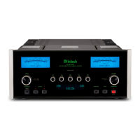
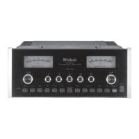
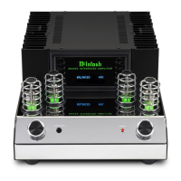
Connecting Components
The MA252 has the ability to automatically switch
power On/Off to McIntosh Source Components via
the Power Control connections. The Data Port Con-
nections allow for the remote operation of basic func-
tions using the MA252 Remote Control.
The connection instructions below, together with
the MA252 Input and Output Connection Diagram on
the next page is an example of a typical audio system.
Your system may vary from this, however the actual
components would be connected in a similar manner.
For additional information refer to “Connector and
Cable Information” on page 6.
Power Control Connections:
1. Connect a Control Cable from the MA252
POWER CONTROL OUTPUT Jack to the Power
Control In on the Turntable.
2. Connect a Control Cable from the McIntosh Turn-
table Power Control Out Jack to the CD Player
Power Control In Jack.
3. Connect any additional McIntosh Components in
a similar manner, as outlined in steps 1 thru 2.
Data Control Connections:
4. Connect a Control Cable from the MA252 DATA
PORT Jack to the CD Player Data In Jack.
5. Connect another McIntosh Component in a similar
manner instead of the CD Player Data In Jack, as
outlined in step 7.
Audio Connections:
6. Connect Balanced Cables from the MA252 BAL-
anced INPUT Connectors to the CD Player Audio
Output.
7. Connect the Audio Cables coming from the
Turntable to the MA252 PHONO Input Jacks (for
a Moving Magnet Cartridge or a Moving Coil
Cartridge with High Audio Output Level).
8. Connect any additional Components in a similar
manner, as outlined in steps 6 and 7.
Ground Connections:
9. Connect the Ground Cable coming from the Turn-
table to the MA252 GND Binding Post.
 Loading...