EasyManuals Logo

McIntosh MA5200 Connection Diagram

McIntosh MA5200
2 pages
To Next Page IconTo Next Page
Page #1 background imageLoading...
Page #1 background image
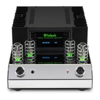
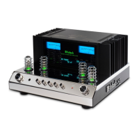
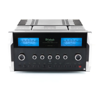
MA5200 Input and Control Connection Diagram
2A
McIntosh Laboratory, Inc. 2 Chambers Street Binghamton, New York 13903-2699 Phone: 607-723-3512 FAX: 607-724-0549 Part No. 04137700
3
Note: Refer to the MA5200 Owner’s Manual page 9 for additional connection
information.
Connection Legend:
Data Cable*- Digital Signal Cable -
Sensor/Keypad Cable - RS232 Cable -
Power Control Cable* - Ground Wire -
Audio Signal Cable - AC Power Cords -
Video Signal Cable - Loudspeaker Cable -
RF Signal Cable -
* 2 conductor shielded with 1/8 inch stereo mini phone plug on each end.
SACD/CD Player
Tur nt abl e
IR Sensor
Computer
(optional Digital Audio Connection)
AM/FM Tuner
30

Other manuals for McIntosh MA5200

Questions and Answers:

Question and Answer IconNeed help?

Do you have a question about the McIntosh MA5200 and is the answer not in the manual?

McIntosh MA5200 Specifications

General IconGeneral
Power Output per Channel100 Watts
Number of Channels2
Total Harmonic Distortion0.005%
Input Impedance20k ohms
Rated Power Band20Hz to 20kHz
Dynamic Headroom1.8dB
Preamplifier OutputYes
Dual Mono Power SupplyNo
USB Input1
Coaxial Input1
Optical Input1
Damping Factor>200
Power Requirement120V 50/60Hz
Digital InputsCoaxial, Optical, USB
Frequency Response+0, -0.5dB from 20Hz to 20kHz +0, -3dB from 10Hz to 100kHz

Related product manuals