EasyManuals Logo

McIntosh MA5200 Connection Diagram

McIntosh MA5200
2 pages
To Previous Page IconTo Previous Page
Page #2 background imageLoading...
Page #2 background image
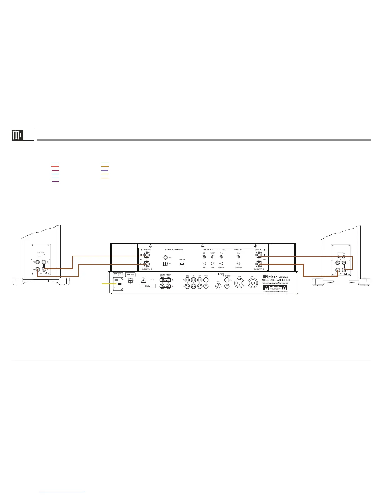
MA5200 Output and Loudspeaker Connection Diagram
2B
Note: Refer to the MA5200 Owner’s Manual pages 9 and 10 for additional connection
information.
Connection Legend:
Data Cable*- Digital Signal Cable -
Sensor/Keypad Cable - RS232 Cable -
Power Control Cable* - Ground Wire -
Audio Signal Cable - AC Power Cords -
Video Signal Cable - Loudspeaker Cable -
RF Signal Cable -
* 2 conductor shielded with 1/8 inch stereo mini phone plug on each end.
Connect to
AC Outlet
Right Loudspeaker Left Loudspeaker
+
-
+
-

Other manuals for McIntosh MA5200

Questions and Answers:

Question and Answer IconNeed help?

Do you have a question about the McIntosh MA5200 and is the answer not in the manual?

McIntosh MA5200 Specifications

General IconGeneral
Power Output per Channel100 Watts
Number of Channels2
Total Harmonic Distortion0.005%
Input Impedance20k ohms
Rated Power Band20Hz to 20kHz
Dynamic Headroom1.8dB
Preamplifier OutputYes
Dual Mono Power SupplyNo
USB Input1
Coaxial Input1
Optical Input1
Damping Factor>200
Power Requirement120V 50/60Hz
Digital InputsCoaxial, Optical, USB
Frequency Response+0, -0.5dB from 20Hz to 20kHz +0, -3dB from 10Hz to 100kHz

Related product manuals