8
FUSE
PUSH
R OUTPUT
8Ω
4Ω
2Ω
8Ω
4Ω
2Ω
L OUTPUT
DATA PORTS
3
1
4
2
IR IN
RS232
EXT
CTRL
MAIN
TRIG 1
TRIG 2
MA8950 INTEGRATED AMPLIFIER
McINTOSH LABORATORY, INC., BINGHAMTON, NY
HANDCRAFTED IN USA WITH US AND IMPORTED PARTS
POWER CONTROL
OUTPUTS
PASSTHRU
INPUT
SERVICE
PORT
CLASS 2
WIRI
NG CLASS 2
WIRI
NG
2
L
R
FIXED
1 PWR AMP 1 2 3 4 5
GND
6
R
MC
MM
L
R
L
CAUTION
RISK OF ELECTRIC SHOCK
DO NOT OPEN
SERIAL
NUMBER
120V 50/60Hz
4.4A
T 6.3AL 250V
UNBALANCED
INPUTS
PHONO BALANCED
OUTPUTS
USB AUDIO
DA2 DIGITAL AUDIO MODULE
HDMI (ARC)
COAX 2
COAX 1
MCT
OPTICAL 2OPTICAL 1
DIGITAL AUDIO INPUTS
SERIAL
NUMBER
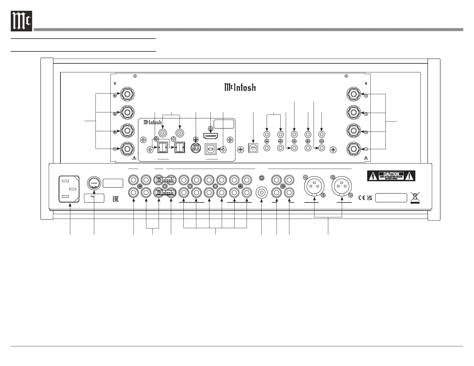
1. Main Power: Attach the included power cable here.
2. Main Fuse Holder: This is where the main fuse to
power the unit is located.
3. Fixed Outputs: An RCA connector cable will
produce a fixed, non-adjustable Volume level signal
from here.
4. Outputs (1 and 2): Use these ports with an RCA
cable to send the signals to a subwoofer or power
amplifier. Connect included Jumper Plugs (see next
page) to Output 1 and PWR AMP to use onboard amp
(see Page 16).
5. PWR AMP Input: The included Jumper Plugs (see
next page) connect Output 1 to the onboard power
amplifier (see Page 16). Also used as a loop for room
correction with Outputs 1 and 2.
6. Unbalanced Inputs (1-6): You can connect up
to six high-level unbalanced signals using an RCA
connection with these ports.
7. GND Input: This is where you would put a ground
wire from a turntable to prevent noise.
8. MC Phono Input: A turntable with a moving coil
cartridge will plug in here with an RCA cable.
9. MM Phono Input: A turntable with a moving
magnet cartridge will plug in here with an RCA cable.
10. Balanced Inputs: Plug in an XLR connector cable
(see next page) to these ports for balanced signals.
11. Loudspeaker Output Terminal Posts: Connect
loudspeakers to these posts (see Page 10).
12. Optical Inputs (1 and 2): These ports accept
optical connections for digital signals.
13. Coax Inputs (1 and 2): You will connect coaxial
cables for digital signals into these ports.
Navigating the Rear Panel
1
2
3
4 5
6
7 8
9
10
11
12
13 14
15
16
17
18
19
20
21
22
11
23
 Loading...