SCHEMATIC NOTES
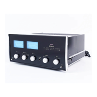
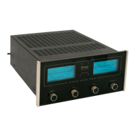
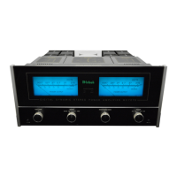
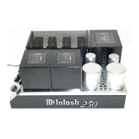
MC 250
1. Unless otherwise specified: Resistance values are in ohms, 1/2 watt, and
10% tolerance; capacitance values smaller than 1 are in microfarads (µF);
capacitance values greater than 1 are in picofarads (pF); inductors are in
mi c rohen r i es (µH).
2. Printed circuit board components are outlined on the schematics by dotted
lines. The circled numbers on the dotted lines correspond to the numbers
on the PC Board layouts.
3. The heavy lines on the schematics denote the primary signal path.
4. All voltages indicated on the schematics are measured under the following
conditions :
a. Use of an 11 megohm impedance VTVM.
b. All voltages ±10% with respect to chassis ground.
c. No signal at input terminals.
d. AC input at 117 volts, 50/60Hz.
e. Front panel controls at:
Left Gain
Right Gain
Mode
Fully CCW
Fully
CCW
Stereo
5. In units with Serial No.'s below 28L21: R88, R89, R90 & R91 are used;
R49 & R50 are 2200W; R86 & R87 are 160W; and R33 & R34 are 33k.
6. In units with Serial No.'s from 28L60 to 37L75, C5 & C6 are 180pF.
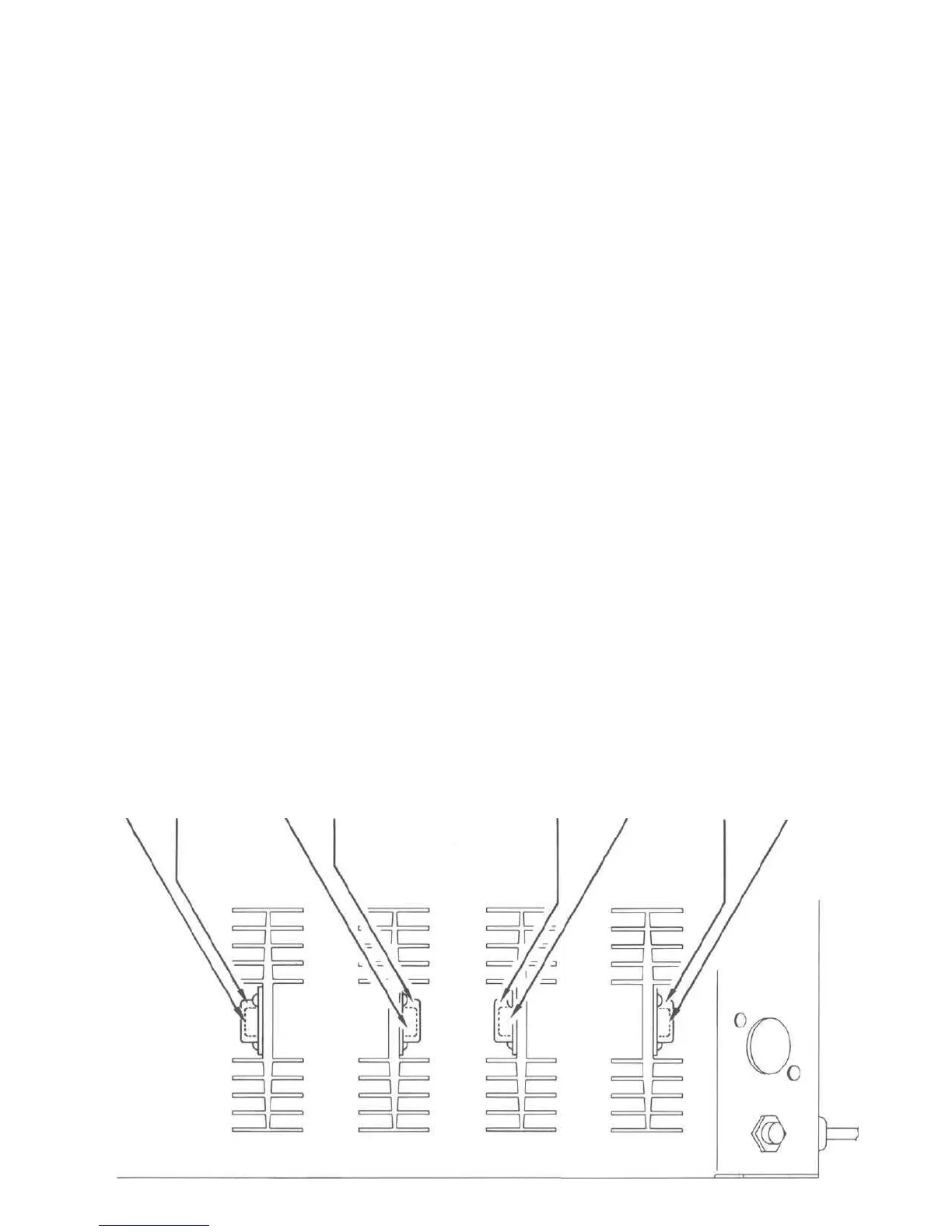
Q21 Q25
BOTTOM TOP
Q19 Q23
BOTTOM TOP
Q20
BOTTOM
LOCATION OF TRANSISTORS NOT ON PRINTED CIRCUIT BOARDS
Q26
TOP
Q22
BOTTOM
Q24
TOP
 Loading...