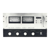
METER RANGE
The METER RANGE switch has five positions.
WATTS
In the WATTS position each meter's primary
calibration is from .005 watt (five milliwatts), up to
500 watts, the rated power output of the MC 2500.
The meter is calibrated for 1000 watts at the right
hand end of the meter scale. While the MC 2500 can-
not reach this power level continuously, it is possi-
ble for short interval peaks to exceed, considerably,
the 500 watt continuous rating.
HOLD
In the HOLD position, each meter indicates
WATTS and locks to the highest power peak in a se-
quence of peaks. The meter will be driven to max-
imum power and electronically held there until a
higher peak passes through the amplifier. If no fur-
ther peaks are reached the meter needle will very
slowly return to its rest position at a decay rate of 6
dB per minute.
DECIBELS (dB)
In the other three positions of the METER RANGE
switch the meters will indicate the output of each
channel in DECIBELS relative to 500 watts or any
other chosen reference.
0 dB In this position of the switch, if the ampli-
fier delivers 500 average watts, the meter in-
dicates 0 dB; at 250 average watts the meter
indicates - 3 dB. If the amplifier is overdriv-
en to + 2 dB the indicated output would be
792 watts.
-10 dB In this position of the switch, if the ampli-
fier delivers 50 average watts, the meter in-
dicates 0 dB; at 25 average watts the meter
indicates -3 dB.
-20 dB In this position of the switch, if the ampli-
fier delivers 5 average watts, the meter in-
dicates 0 dB; at 2.5 average watts the meter
indicates -3 dB.
POWER GUARD
POWER GUARD assures that the MC 2500 cannot
be overdriven, thus amplifier output clipping is
eliminated. Clipping is caused when an amplifier is
asked to produce more power output than it can de-
liver with low distortion. Amplifiers are capable of
delivering large quantities of highly distorted power
when they are driven to clipping. The extra energy
content of the clipped signal will damage most
speakers. Mcintosh's Power Guard circuit protects
your speakers from this kind of damage. The MC
2500 has a built in "waveform comparator" that com-
pares the wave shape of the output signal to the in-
put signal. If the disparity between the two signals,
due to overdrive, exceeds 0.5% (equivalent to 0.5%
total harmonic distortion) a red LIMIT indicator il-
luminates. With any further increase in distortion
the Power Guard circuit operates to limit the
amplifier input dynamically so that the amplifier
cannot be overdriven. Power Guard eliminates
amplifier output clipping. As long as the amplifier
operates without overload the NORMAL indicator il-
luminates.
HEADPHONES
The output of the front panel HEADPHONES jack
has been designed to feed low impedance dynamic
stereo headphones.
The HEADPHONES output is not affected by the
SPEAKERS switch.
SPEAKERS
OFF: The loudspeakers are turned off when the
SPEAKER switch is in the OFF position and the red
speaker indicator is on.
ON: Music will be heard through the loudspeak-
ers. Use this as the normal listening position. A
green speaker light indicates when the speakers are
ON.
THE SPEAKER SWITCH MUST BE IN THE "ON" POSI-
TION TO HEAR MUSIC FROM THE LOUDSPEAKERS.
POWER
The power switch turns the MC 2500 ON or OFF. The
power switch is also a power input circuit breaker. If
the power input to the amplifier exceeds a safe limit
the circuit breaker will trip off. To restore power sim-
ply place the switch in the OFF position and then to
the ON position.
-9-
 Loading...