Do you have a question about the McIntosh MC252 and is the answer not in the manual?
Essential safety guidelines for operating the McIntosh MC252 amplifier, including handling, placement, and electrical safety.
Instructions on using accessories, moving the unit, unplugging during storms, and referring servicing to qualified personnel.
Caution regarding the MC252's weight (94.5 lbs) and the need for two or more persons for safe handling.
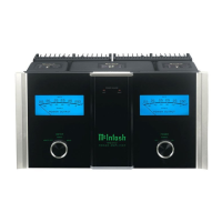
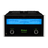
Covers power output, autoformers, power guard, sentry monitor, remote power control, and meters.
Emphasis on providing adequate ventilation for cool operation to ensure longevity and avoid heat-generating components.
Description of the MODE switch for selecting Stereo, Mono Bridged, or Mono Bi-Amp operation.
Instructions for connecting wires, spade lugs, or banana plugs to output terminals, matching impedance and polarity.
Connecting loudspeaker cables to specific output terminals for 4, 8, or 16 ohm loads, observing polarity.
Connecting loudspeaker cables and jumper wires to output terminals for 1, 2, or 4 ohm loads.
Details on the Sentry Monitor output transistor protection circuit ensuring safe operation under extreme conditions.
Explanation of the Power Guard circuit preventing clipping, its waveform comparison, and PG light activation.
Detailed specifications for Stereo, Mono Bridged, and Mono Bi-Amp power output into various ohm loads.
| Power Output per Channel | 250 watts |
|---|---|
| Number of Channels | 2 |
| Total Harmonic Distortion | 0.005% |
| Frequency Response | 20Hz to 20kHz |
| Signal to Noise Ratio | 112dB |
| Damping Factor | >40 |
| Dimensions | 17-1/2" (44.5cm) wide, 7-5/8" (19.4cm) high (including feet), 20" (50.8cm) deep (including front panel and cables) |
| Weight | 75 lbs (34.1 kg) net, 93 lbs (42.2 kg) in shipping carton |
| Power Output per Channel @ 2, 4 or 8 Ohms | 250 watts |
| S/N Ratio | 112dB |
| Dynamic Headroom | 1.8dB |
| Rated Power Band | 20Hz to 20kHz |
| Input Impedance | 10k ohms (balanced), 20k ohms (unbalanced) |
| Frequency Response (+0, -0.25dB) | 20Hz to 20kHz |
| Input Sensitivity | 2.5V |
| Output Impedance | 2, 4, 8 Ohms |