Do you have a question about the McIntosh MC2000 and is the answer not in the manual?
Key electrical parameters: power output, distortion, frequency response, impedance, and damping factor.
Details input sensitivity, tube compliment, and power requirements for the amplifier.
Covers amplifier dimensions, finish specifications, and weight information.
Notes on signal path indication, voltage measurement conditions, and component value units.
Warning regarding critical components marked with a symbol; use manufacturer-recommended replacements.
Shock hazard warning: Do not open. Replace fuses only with same type and rating.
Identifies transformers, meter lamp PCBs, meter PCBs, logo lamp PCBs, switch, and lamp PCBs.
Identifies AC power PCB, SW remote PCB, output PCBs, power supply PCBs, main amp PCBs, input PCBs, and bias control PCBs.
Illustrates signal flow from inputs through driver stages to output stages.
Details power input, transformers, voltage regulation, and DC supplies.
Diagram showing wiring between lamp, remote, bias control, and meter circuits.
Diagram showing wiring between power supply, AC power, remote, and output circuits.
Parts in shaded area have critical characteristics; use manufacturer replacements.
Highlights the primary and balanced signal paths within the main amplifier circuit.
Parts in shaded area have critical characteristics; use manufacturer replacements.
Parts in shaded area have critical characteristics; use manufacturer replacements.
Parts in shaded area have critical characteristics; use manufacturer replacements.
Details power input and connections for the switch remote PCB.
Shows connections for selecting input sensitivity (BAL/UNBAL).
Details ICs, transistors, and controls related to the meter function.
Lists parts required for packing the power amplifier, including poly bag, foam pads, and rings.
Lists part number for the tube carton (gold) with foam pads.
Lists parts for accessory carton, including inside/outside cartons and foam pad set.
| Total Harmonic Distortion (THD) | 0.5% |
|---|---|
| S/N Ratio | 100dB |
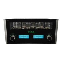
| Type | Tube Amplifier |
| Frequency Response | 20Hz - 20kHz (+0, -0.5dB) |
| Output Impedance | 4, 8 Ohms |
| Tubes | 8 x KT88, 4 x 12AX7 |