10
Caution: Do not connect the AC Power Cord to the
MC452 Rear Panel until after the Loudspeaker
Connections are made and the protective Termi-
nal Connections Covers are installed. Failure to
observe this could result in Electric Shock.
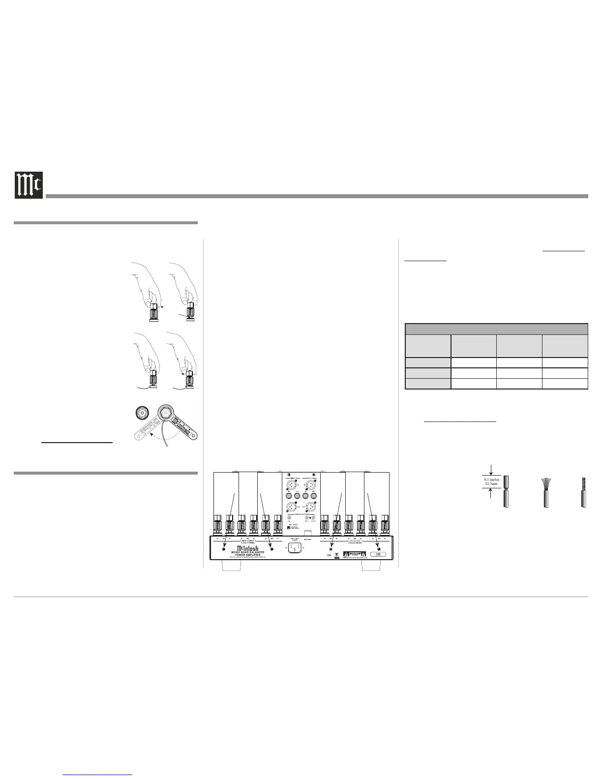
The connection instructions below, together with the
MC452 Connection Diagram located on the separate
folded sheet “Mc1B”, is an example of a typical audio
system. Your system may vary from this, however the
actual components would be connected in a similar
This McIntosh MC452 Quad Balanced Power Ampli-
fier is designed for Loudspeakers with an impedance
of 2 ohms, 4 ohms or 8 ohms. Connect a single Loud-
speaker only to the Right and Left Output Terminals.
When connecting Loudspeakers to the MC452 it
is very important to use cables of adequate size, so
there is little to no power loss in the cables. The size is
specified in Gauge Numbers or AWG (American Wire
Gauge). The smaller the Gauge number, the larger the
wire size:
Loudspeaker Cable Distance vs Wire Gauge Guide
Loudspeaker
Impedance
25 feet
(7.62 meters)
or less
50 feet
(15.24 meters)
or less
100 feet
(30.48 meters)
or less
2 Ohms
12AWG 10AWG 8AWG
4 Ohms
14AWG 12AWG 10AWG
8 Ohms
16AWG 14AWG 12AWG
6. Prepare the Loudspeaker Hookup Cable for attach-
ment to the MC452 Power Amplifier:
Bare wire cable ends:
Carefully remove sufficient insulation from the
cable ends, refer to figures 2, 3 & 4. If the cable
is stranded, carefully twist the strands together
as tightly as possible.
Notes: 1. If desired, the twisted ends can be tinned
with solder to keep the strands together.
2. The prepared bare wire cable ends may be
inserted into spade lug connectors for use
in outside the United States and Canada
only.
3. Banana plugs are for use in the United
States and Canada only.
manner. For additional information refer to “Connec-
tor and Cable Information” on page 4.
1. For Remote Power Control, connect a power control
cable from the Audio Preamplifier or A/V Con-
trol Center Power Control Output 1 to the MC452
POWER CONTROL IN Amplifier One.
2. Connect a power control cable from Amplifier One
Power Control OUTput 1 to the MC452 POWER
CONTROL IN Amplifier Two.
3. Connect XLR cables from the Balanced Output 1
(L&R) of an Audio Preamplifier or A/V Control
Center to the MC452 Balanced INput (RIGHT and
LEFT). Place the INPUT MODE Switch in the
BALANCED Position.
Note: An optional hookup is to use unbalanced
cables and place the INPUT MODE Switch in
the UNBALANCED Position.
4. Connect XLR cables from Amplifier One Audio
Balanced OUTput (LEFT and RIGHT) to the
MC452 Balanced INput (RIGHT and LEFT). Place
the INPUT MODE Switch in the BALANCED
Position.
5. Using a suitable tool remove the four screws from
the MC452 Rear Panel and temporarily place them
in a safe place. Refer to figure 1.
Figure 1
Remove Screws
Remove Screws
How to Connect for Bi-Amp
When connecting the Loudspeaker Hookup Cables to
the MC452 Power Amplifier Output Terminals please
follow the steps below:
1. Rotate the top of the Output Terminal Post coun-
terclockwise until an opening
appears. Refer to gures A and
B.
2. Insert the Loudspeaker hookup
cable into the Output Terminal
Post opening or the cable spade
lug around the center post of
the Output Terminal. Refer to
gure C.
3. Rotate the top of the Output
Terminal Post clockwise until it
is nger tight. Refer to gure D.
4. Place the supplied McIntosh
Wrench over the top of the Out-
put Terminal and rotate it one
quarter of a turn (90° ) to secure
the Loudspeaker Cable Connec-
tion. Do not over tighten. Refer
to gure E.
Output Terminals
Figure A
 Loading...