15
optimum, causes
more output cur-
rent to flow, which
results in extra heat
being generated in
the power output
stage. This increase
in temperature will
result in a reduced
life expectancy for
the amplifier.
The special
Balanced Winding
Autoformer cre-
ates an ideal match
between the power
amplifier output
stage and
the loud-
speaker.
Refer to
figure 16.
There is absolutely no performance limita-
tion with an Autoformer. Its frequency re-
sponse exceeds that of the output circuit itself,
and extends well beyond the audible range. Its
distortion level is so low it is virtually impos-
sible to measure.
In the rare event of a power amplifier out-
put circuit failure, the McIntosh Autoformer
provides absolute protection from possible
damage to your valuable loudspeakers. The
unequaled expertise of McIntosh in the design
and manufacturing of Autoformers is legend-
ary in the high fidelity industry. McIntosh
engineers know how to do it right.
transfer at frequencies from below 20Hz to well
beyond 20,000Hz with optimum impedance points of
two ohms, four ohms and eight ohms. The unequaled
expertise of McIntosh in the design and manufactur-
ing of autoformers is legendary in the high fidelity
indust ry.
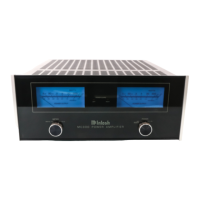
The high efficiency circuit design of the MC452
contributes to low operating temperatures. More than
2800 square inches of heat sink area keep the MC452
operating safely with convection cooling. No fans are
needed. Refer to figure 14.
Autoformers
All solid state power amplifier output circuits work
best into what is called an optimum load. This op-
timum load may vary considerably from what a
loudspeaker requires. In the case of more than one
loudspeaker connected in parallel, the load to the
power amplifier may drop to two ohms or even less. A
power amplifier connected to a load that is lower than
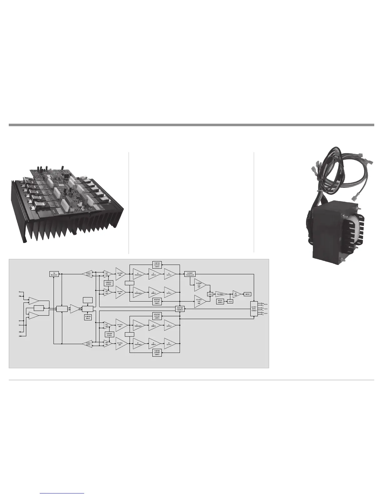
Technical Description
Block Diagram
of the
Power Amplifier
(one channel shown)
Figure 15
 Loading...