6
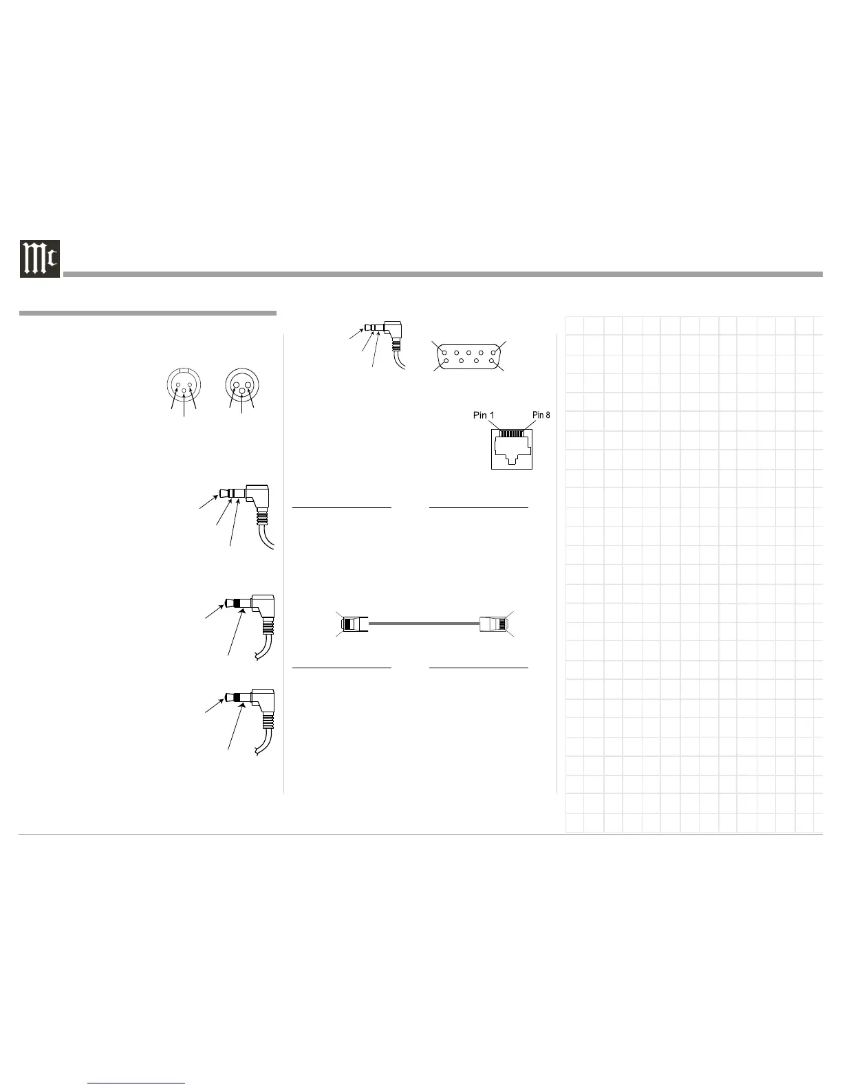
Ethernet RJ45 Socket
1. Transmit Data (+) 5. N/C
2. Transmit Data (-) 6. Receive Data (-)
3. Receive Data (+) 7. N/C
4. N/C 8. N/C
Ethernet Cable - Straight Thru Connections
Pin Number - Wire Color Pin Number - Wire Color
1. Orange/White → 1. Orange/White
2. Orange → 2. Orange
3. Green/White → 3. Green/White
4. Blue → 4. Blue
5. Blue/White → 5. Blue/White
6. Green → 6. Green
7. Brown/White → 7. Brown/White
8. Brown → 8. Brown
Ethernet Cable - Crossover Connections
Pin Number - Wire Color Pin Number - Wire Color
1. Orange/White → 1. Green/White
2. Orange → 2. Green
3. Green/White → 3. Orange/White
4. Blue → 4. Blue
5. Blue/White → 5. Blue/White
6. Green → 6. Orange
7. Brown/White → 7. Brown/White
8. Brown → 8. Brown
XLR Connectors
Below is the Pin configuration for the XLR Balanced
Output Connectors on the MX122. Refer to the dia-
grams for connections.
PIN 1: Shield/Ground
PIN 2: + Signal
PIN 3: - Signal
TRIGger (Power Control) Connectors
The MX122 Trigger Output Jacks send an On/Off
signal from 0 to +12 volts with a total current up to
50mA when connected to
other Components. A 3.5mm
stereo mini phone plug is
used for connection to the
Trigger Outputs on the
MX122.
Data Output
The MX122 Data Out sends
Remote Control Signals to
Source Components. A 3.5mm
mini phone plug is used for
connection.
IR In Port Connector
The IR IN Port also uses a
3.5mm mini phone plug and al-
lows the connection of external
IR Receivers to the MX122.
RS232 Connector
The RS232 Data Cable is a 3.5mm stereo mini phone
plug to a subminiature DB 9 connector.
Connector and Cable Information
PIN 1
PIN 2
PIN 3
Connector and Cable Information
Pin 1
Pin 8
Pin 1
Pin 8
PIN 2