3
1. The heavy lines on the schematic denote the primary
signal path.
2. Unless otherwise noted, all voltages indicated on the
schematics are measured under the following conditions:
a. AC input at 120 volts, 50/60Hz.
b. All voltages are +/-10% with respect to ground. A
high impedance (10 megaohm) voltmeter must be used.
4. On PC board drawings, Square pad indicates:
a. Polarized Capacitors - Positive
b. Diodes - Cathode
c. Others - Pin 1
5. WARNING
Parts marked with the symbol have critical
characteristics. Use only replacement parts recom-
mended by the manufacturer.
NOTES
Output Impedance
47 ohms at all outputs
Maximum Output Voltage
9.5 Vrms
Total Harmonic Distortion
0.005% at all outputs
Sensitivity
Analog Input: 400mV for 2.0V output
Signal To Noise Ratio – All Outputs
Greater than 90dB un-weighted. Greater than 100dB A
weighted. Greater than 98dB CCIR.
Maximum Input Signal
Analog Input: 6Vrms
Voltage Gain
Analog Input to Output: 14Db
Frequency Response
+0, -0.5dB from 20Hz to 20,000Hz
Tone Controls
+12dB, -12dB from flat setting
General Specifications
Power Requirements
100 Volts, 50/60Hz at 65 watts
110 Volts, 50/60Hz at 65 watts
120 Volts, 50/60Hz at 65 watts
220 Volts, 50/60Hz at 65 watts
230 Volts, 50/60Hz at 65 watts
240 Volts, 50/60Hz at 65 watts
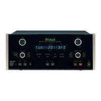
NOTE: Refer to the rear panel of the MX134 for the correct
voltage.
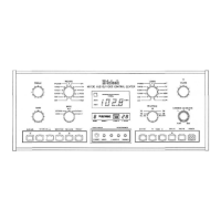
Overall Dimensions
Front Panel: 17-1/2 inches (44.5cm) wide, 7-5/8 inches
(19.37cm) high. Depth behind front mounting panel is 21
inches (53.3cm) including clearance for connectors. Panel
clearance required in front of mounting panel is 1-1/8 inches
(2.9cm).
Weight
32.5 pounds (14.8kg) net, 51.5 pounds (23.4kg) shipping
weight
PERFORMANCE SPECIFICATIONS con’t
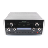
MX134
 Loading...