62 AGR 070A through 100A IOMM AGR-1
Digital Inputs
All Digital Inputs are 24 Vac. At 7.5 Vac to 24 Vac the digital input contacts are considered closed.
Below 7.5 Vac, the contracts are considered open. See Table 19 for details and operating
characteristics.
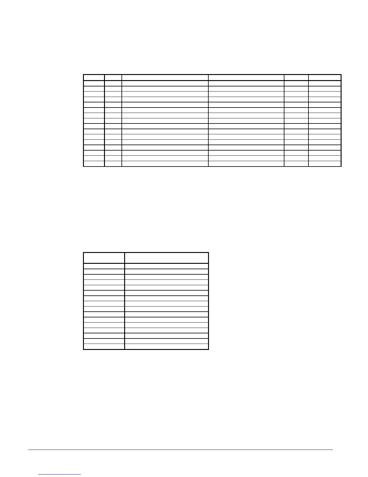
Table 19, Digital Inputs
Input LED Description Circuit Closed Open
0 0 Mechanical High Pressure Switch Circuit #1 Normal Alarm
1 1 Oil differential switch Compressor #1 normal Alarm
2 2 Motor Protection Switch Compressor #1 Normal Alarm
33
44
5 5 System Switch Unit Run Stop
6 6 Phase/Voltage Monitor Unit Normal Alarm
7 7 Pumpdown Switch Unit Pmp Dn Normal
8 8 Mechanical High Pressure Switch Circuit #2 Normal Alarm
9 9 Oil Differential Switch Compressor #2 Normal Alarm
10 10 Motor Protection Switch Compressor #2 Normal Alarm
11 11
12 12
13 13 Chiller Remote Stop Switch Unit Run Stop
14 14 Evap Water Flow Switch Unit Run Stop
15 15 Pumpdown Switch Circuit #2 Pmp Dn Normal
Relay Board Outputs
All of the MicroTech panel outputs are controlled by solid-state relays which are driven by the model
250 controller. The controller activates a solid-state relay by sending a “trigger” signal to the output
board via the attached ribbon cable. The relay responds to the trigger by lowering it’s resistance
which allows current to flow through it’s “contacts”. When the controller removes the trigger signal,
the relay’s resistance becomes very high, causing the current flow to stop. The outputs are
individually protected by a 5 amp fuse mounted on the output board adjacent to each relay. Table 20
provides additional information about each output. Refer to the MicroTech Staging schematic for
digital output wiring.
Table 20, Relay Board Outputs
Digital Output
Number
Output
Description
0 Alarm Circuit
1 Chilled Water Pump Relay
2 Liquid Line Solenoid Circuit #1
3 Liquid Line Solenoid Circuit #2
4 Compressor #1 Circuit #1
5 Compressor #2 Circuit #2
6 Compressor #1 Unloader #1
7 Compressor #2 Unloader #1
8 Compressor #1 Unloader #2
9 Compressor #2 Unloader #2
10 Condenser Fan (M11)
11 Condenser Fan (M12)
12 Condenser Fan (M13)
13 Condenser Fan (M21)
14 Condenser Fan (M22)
15 Condenser Fan (M23)
Reset Options
User reset options are located in the “Leaving Water Setpoint” menu. The options are:
None
“None” is the default value and the leaving evaporator water temperature controls the unit.
Return
When selecting “Return” as the reset mode, the controller resets the leaving water temperature set
point as required to maintain the selected return water temperature.

 Loading...


