IM 422 / Page 2 of 28
Table of Contents
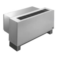
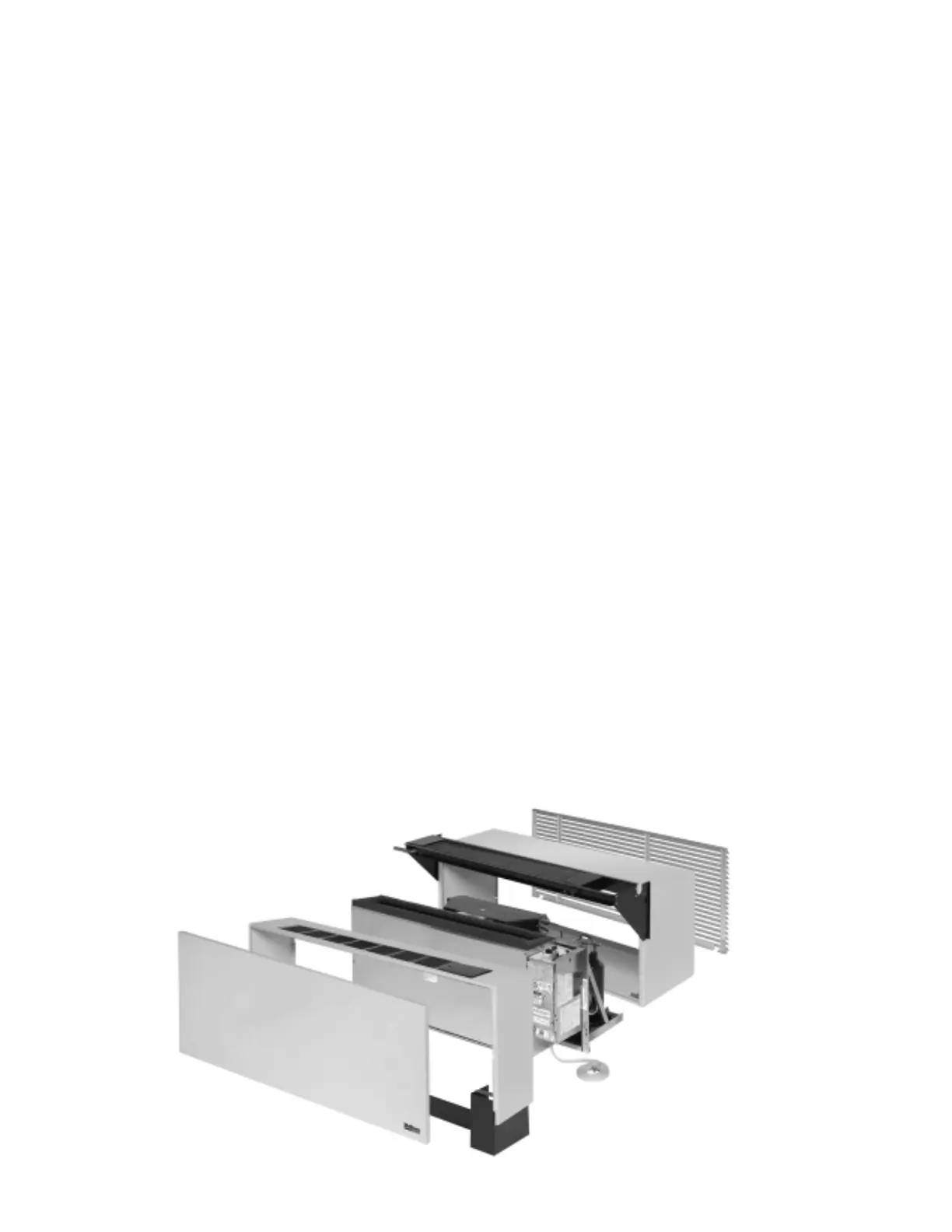
Figure 1. Exploded view of complete unit
Installation. . . . . . . . . . . . . . . . . . . . . . . . . . . . . . . . . . . . . . . 2
Inspection . . . . . . . . . . . . . . . . . . . . . . . . . . . . . . . . . . . . . . . 2
Nomenclature . . . . . . . . . . . . . . . . . . . . . . . . . . . . . . . . . . . . 3
Wall Opening Requirements . . . . . . . . . . . . . . . . . . . . . . . . 3
Wall Sleeve Installation . . . . . . . . . . . . . . . . . . . . . . . . . . 4–6
Panel Wall With Factory Louver . . . . . . . . . . . . . . . . . . . . 4
Panel Wall With Continuous Louver . . . . . . . . . . . . . . . . . 5
Frame and Brick Construction . . . . . . . . . . . . . . . . . . . . . 6
Heat Section Installation. . . . . . . . . . . . . . . . . . . . . . . . . . . . 7
Coil Piping. . . . . . . . . . . . . . . . . . . . . . . . . . . . . . . . . . . . . . . 7
Steam Coils . . . . . . . . . . . . . . . . . . . . . . . . . . . . . . . . . . . . 7
Hot Water Coils . . . . . . . . . . . . . . . . . . . . . . . . . . . . . . . . . 7
Wall Mounted Thermostats . . . . . . . . . . . . . . . . . . . . . . . 8-9
Wireless Remote (Option) . . . . . . . . . . . . . . . . . . . . . . . . . 10
Thermostat Wiring Configurations . . . . . . . . . . . . . . . . 10-11
Anchoring . . . . . . . . . . . . . . . . . . . . . . . . . . . . . . . . . . . . . . 12
Installing Louvers . . . . . . . . . . . . . . . . . . . . . . . . . . . . . . . . 12
Installation of Cooling Chassis . . . . . . . . . . . . . . . . . . . . . . 13
Adjusting Temperature Limiting Device . . . . . . . . . . . . . . . 13
Electrical Service . . . . . . . . . . . . . . . . . . . . . . . . . . . . . . . . 13
Installing Room Cabinet . . . . . . . . . . . . . . . . . . . . . . . . . . . 13
Equipment Start-up. . . . . . . . . . . . . . . . . . . . . . . . . . . . . . . 14
Scheduled Maintenance . . . . . . . . . . . . . . . . . . . . . . . . . . . 14
Recommended Spare Parts . . . . . . . . . . . . . . . . . . . . . . . . 15
Refrigeration Cycle . . . . . . . . . . . . . . . . . . . . . . . . . . . . . . . 15
Troubleshooting Chart . . . . . . . . . . . . . . . . . . . . . . . . . 16–17
Approximate Shipping Weights . . . . . . . . . . . . . . . . . . . . . 17
Wiring Diagrams . . . . . . . . . . . . . . . . . . . . . . . . . . . . . . 18–27
Normally Closed Valve (Steam) . . . . . . . . . . . . . . . . . . . 18
Normally Open Valve (Hot Water) . . . . . . . . . . . . . . . . . 19
Digital Touch-pad Control Wiring . . . . . . . . . . . . . . . . . . 20
PDNS/PDNC Control Remote Thermostat
(N.O. Valve - 24V). . . . . . . . . . . . . . . . . . . . . . . . . . . . . . 21
PDNS/PDNC Control Unit Mounted
(N.O. Valve - 24V). . . . . . . . . . . . . . . . . . . . . . . . . . . . . . 22
Need Heading Description . . . . . . . . . . . . . . . . . . . . . . . 23
PDNS/PDNC Control Remote Thermostat
(N.C. Valve - 24V) . . . . . . . . . . . . . . . . . . . . . . . . . . . . . . 24
PDNS/PDNC Unit Mounted Thermostat
(Manual Changeover, N.C. Valve) . . . . . . . . . . . . . . . . . 25
PDNS/PDNC Control Unit Mounted with HFLO Fan
Cycle on Heat (N.C. Valve - 24V) . . . . . . . . . . . . . . . . . . 26
PDNS/PDNC Unit Mounted Thermostat
(Manual Changeover, N.C. Valve) . . . . . . . . . . . . . . . . . 27
Installation
The installation of this equipment shall be in accordance with the regulations of authorities having jurisdiction and all
applicable codes. It is the responsibility of the installer to determine and follow the applicable codes. Sheet metal parts,
self-tapping screws, clips, and such items inherently have sharp edges, and it is necessary that the installer exercise
caution. This equipment is to be installed only by an experienced installation company which employs trained
personnel.
Inspection
When the equipment is received, all items should be carefully
checked against the bill of lading to be sure all crates and
cartons have been received. All units should be carefully inspected
for damage when received. If any damage is noticed, the carrier
should make the proper notation on the delivery receipt acknowl-
edging the damage. The carrier should also fill out a Carrier
Inspection Report. The McQuay International Traffic Department
should then be notified.
The unit nameplate should be checked to make sure the
voltage agrees with the power supply available.
This unit is designed and built for through-the-wall installa-
tion in either new or existing buildings. The self-contained
refrigerant system delivers cooling to the desired space. Heat-
ing is accomplished with a top mounted hydronic heating coil.
Each conditioner consists of the following components:
1. Cooling Chassis — Shipped separate in a single carton.
2. Wall Sleeve — Shipped separate in a single carton or in a
multi-pack of 15.
3. Hydronic Heat Section — Shipped in a separate carton.
4. Outdoor Louver — Shipped in a separate carton.
5. Room Cabinet — Shipped in a separate carton with kickplate
attached.