IM 422 / Page 3 of 28
1
1
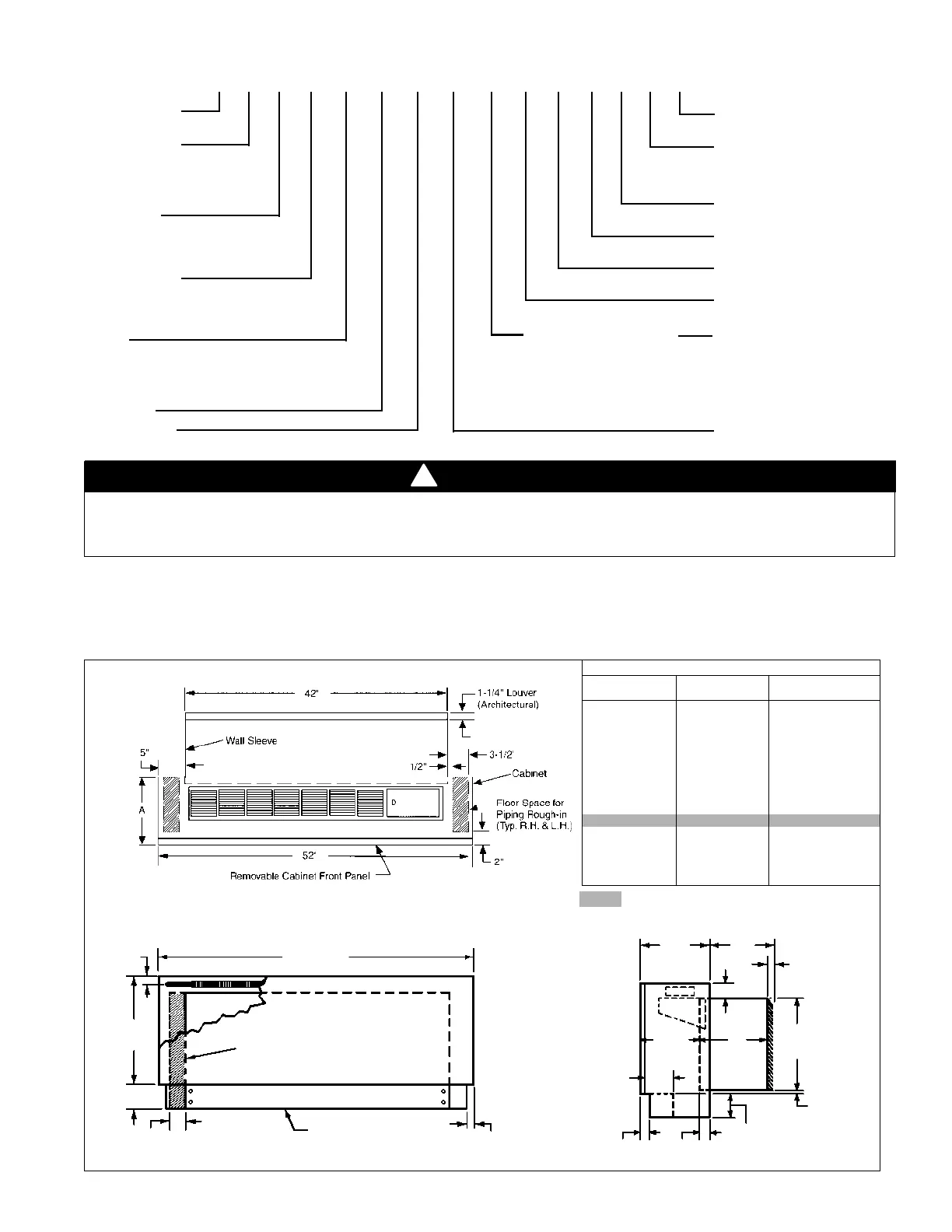
⁄4" RECESS FOR ARCHITECTURAL LOUVER
“A” – IN. (MM) “D” – IN. (MM) “B” – IN. (MM)
ROOM CABINET WALL SLEEVE WALL THICKNESS
18
3
⁄4 (476) 13
3
⁄4 (349) 4
3
⁄4–5
3
⁄4 (121–146)
17
3
⁄4 (451) 13
3
⁄4 (349) 5
3
⁄4–6
3
⁄4 (146–171)
16
3
⁄4 (425) 13
3
⁄4 (349) 6
3
⁄4 –7
3
⁄4 (171–197)
15
3
⁄4 (400) 13
3
⁄4 (349) 7
3
⁄4 –8
3
⁄4 (197–222)
14
3
⁄4 (375) 13
3
⁄4 (349) 8
3
⁄4 –9
3
⁄4 (222–248)
13
3
⁄4 (349) 13
3
⁄4 (349) 9
3
⁄4 –10
3
⁄4 (248–273)
12
3
⁄4 (324) 13
3
⁄4 (349) 10
3
⁄4 –11
3
⁄4 (273–298)
11
3
⁄4 (298) 13
3
⁄4 (349) 11
3
⁄4 –12
3
⁄4 (298–324)
10
3
⁄4 (273) 13
3
⁄4 (349) 12
3
⁄4 –13
3
⁄4 (324–349)
10
3
⁄4 (273) 14
3
⁄4 (375) 13
3
⁄4 –14
3
⁄4 (349–375)
10
3
⁄4 (273) 15
3
⁄4 (400) 14
3
⁄4 –15
3
⁄4 (375–400)
10
3
⁄4 (273) 16
3
⁄4 (425) 15
3
⁄4 –16
3
⁄4 (400–425)
10
3
⁄4 (273) 17
3
⁄4 (451) 16
3
⁄4 –17
3
⁄4 (425–451)
Product Category
P = PTAC
Product Identifier
DNS = A/C w/Top-Mnt Hyd Heat
(Flat Top)
DNC = A/C w/Top-Mnt Hyd Heat &
Corrosion Protection
Design Series
1 = A Design 4 = D Design
2 = B Design 5 = E Design
3 = C Design
Nominal Capacity
007 = 7,000 015 = 15,000
009 = 9,000 016 = 16,000
012 = 12,000
Voltage
A = 115-60-1
C = 206-60-1
J = 265-60-1
S = 208-115-60-1
Coil Options
Heating Options
62 = Hydronic, normally open 63 = Hydronic, normally closed
P DNS 1 009 E Z 62 Z 12AR14 C I C 1
Note: Electrical rough-in should be located behind kickplate
(removable front) and below wall sleeve.
52" (1320mm)
1
1
⁄2"
(38mm)
19
1
⁄2"
(495mm)
Wall Space For Piping Rough-in
(Typ. R.H. & L.H.)
3"
(76mm) Min.
3"
(76mm)
Kickplate (Removable
Front)
7
⁄8"
(22mm)
Wall
Thickness
“B”
“A”
1
1
⁄4" (32mm)
2
7
⁄8" (67mm)
16"
(406mm)
“D”
9
1
⁄8"
(232mm)
5
1
⁄2"
(140mm)
7
⁄8" (22mm)
1
5
⁄8"
(41mm)
1
5
⁄16"
(33mm)
3" (76mm) Min.
Kickplate Height
Standard Size Wall Sleeve
Wall Opening Requirements
Before installing the unit, check the wall opening to be sure the
wall sleeve will slide into the opening unobstructed. For ma-
sonry walls, a lintel must be used to provide support over each
opening. The rough opening should measure 16
1
⁄4" (413mm)
high x 42
1
⁄4" (1073mm) wide. The opening must be a minimum
of 3" (76mm) above the finished floor (including carpeting).
Residential and institutional cleaning compounds can cause permanent damage to the packaged terminal unit. To avoid damage to unit controls and heat transfer
surfaces, do not spray cleaning compounds onto the discharge grille, return air opening, or unit controls. Normal cleaning can be accomplished by wiping the unit
surface with a damp cloth. When using cleaning compounds on carpets, floors or walls, turn the unit off to avoid drawing potentially damaging vapors into the package
terminal unit.
!
WARNING
Product Style
1 = 1st Style Change
SKU Type
A = Stock
B = Quick Ship
C = Tailored
Color
I = Antique Ivory
Power Connection
C = Cord
Return Air
14 = Bottom
Discharge
AR = Flat Top
Hand Orientation
Z = Not Applicable
Figure 2. Unit dimensions
Product Nomenclature
Electromechanical Controls Solid State Control
12 = Unit Mount MCO 55 = Unit Mount MCO
13 = Wall T stat 56 = Hand Held Remote Wireless
21 = Unit Mtd. MCO w/Heat 57 = Wall Mounted Remote T'stat
Fan Lockout
26 = Unit Mtd. MCO w/ GRC & NSB
24 = Unit Mtd. MCO w/NSB
 Loading...