8. APPENDIX
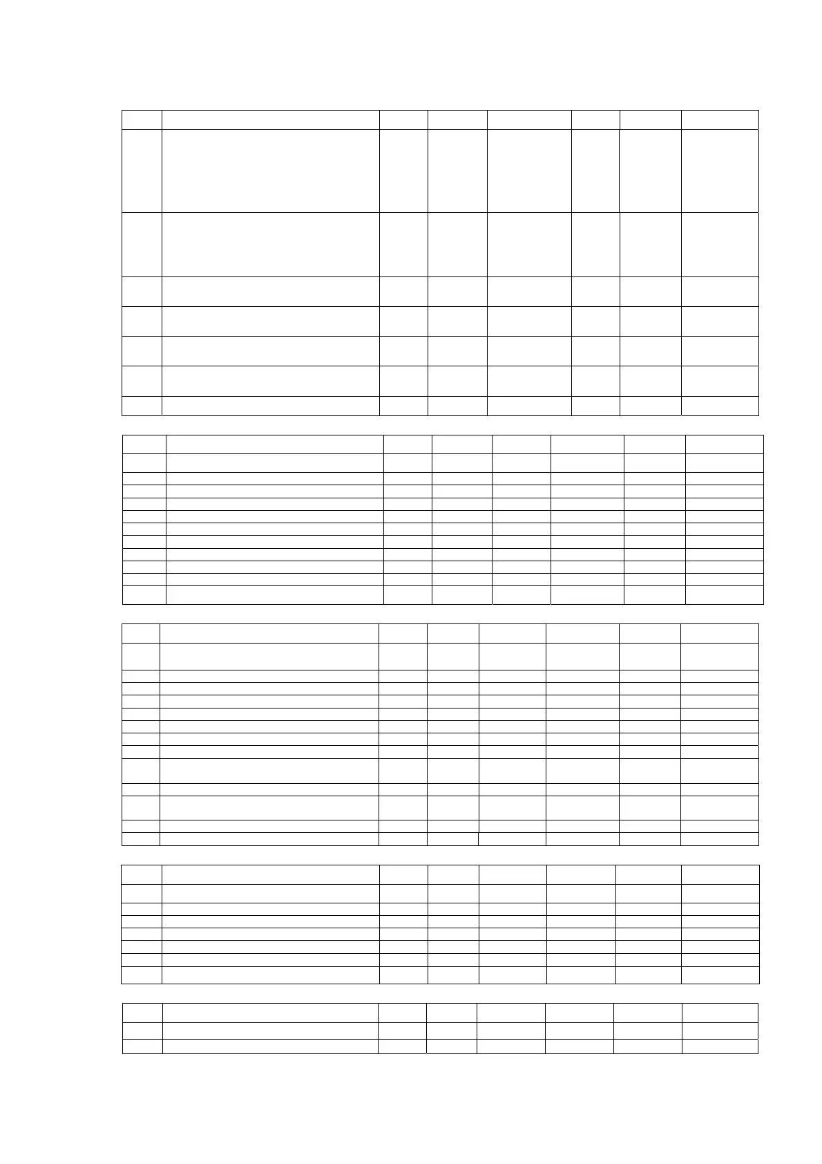
GENERAL Type Unit Default
Min Max Resolution
0 2 1
G1 Model
O=Chiller,
1=Heat Pump,
2=Chiller/ Boiler,
3=Heat pump/Boiler, 4=Chiller+Boiler,
5=Heat pump+Boiler
FFlag4
(Chiller+Boiler)
G2
Number of compressor
1=1 compressor,
2=2 compressor
3=3 compressor,
4=4 compressor
FFlag1 14 1
G3
On/off input
0=disable, 1=enable
FFlag0(disable)01 1
G4
Cool/Heat input
0=disable, 1=enable
F Flag 0 (disable) 0 1 1
G5
External alarm input
0=disable, 1=enable
FFlag0(disable)01 1
G6
Water system for chiller network
0=independent, 1=modular
FFlag0(disable)01 1
G7 Unit number F Flag 0 0 50 1
SENSOR
Type Unit Default Min Max Resolution
S1 Entering water sensor calibration
U
ºC ( F) 0 (0) -12 ( 216) 12 (21.6) 0.1
S2 Leavin
water sensor calibration U °C
°F
0
0
-12
-21.6
12
21.6
0.1
S3 Air sensor calibration U °C
°F
0
0
-12
-21.6
12
21.6
0.1
S4 Defrost
condenser
sensor 1 calibration U °C
°F
0
0
-12
-21.6
12
21.6
0.1
S5 Defrost
condenser
sensor 2 calibration U °C
°F
0
0
-12
-21.6
12
21.6
0.1
S6 Defrost
condenser
sensor 3 calibration U °C
°F
0
0
-12
-21.6
12
21.6
0.1
S7 Defrost
condenser
sensor 4 calibration U °C
°F
0
0
-12
-21.6
12
21.6
0.1
S8 Com
ressor dischar
e sensor 1 calibration U °C
°F
0
0
-12
-21.6
12
21.6
0.1
S9 Compressor dischar
e sensor 2 calibration U °C
°F
0
0
-12
-21.6
12
21.6
0.1
S 10 Com
ressor dischar
e sensor 3 calibration U °C
°F
0
0
-12
-21.6
12
21.6
0.1
S11 Compressor discharge sensor 4 calibration U °C (°F) 0 (0) -12 (-21.6) 12 (21.6) 0.1
REGULATOR Type Unit Default Min Max Resolution
R1 Cooling set-point D °C (°F) 12 (53.6) R5 R6 0.1
R2 Cooling differential U °C (°F) 1.5* (2.7) 0.4 (0.7) 10(18) 0.1
R3 Heating set-point D °C (°F) 40 (104) R7 R8 0.1
R4 Heating differential U °C (°F) 1.5* (2.7) 0.4 (0.7) 10 (18) 0.1
R5 Minimum Cooling set-point U °C (°F) 7 (44.6) -20 (-4) R6 1
R6 Maximum Coolin
set-point U °C
°F
20
68
R5 40
104
1
R7 Minimum Heating set-point U °C (°F) 30 (86) -20 (-4) R8 1
R8 Maximum Heating set-point U °C (°F) 50 (122) R7 90 (194) 1
R9
Auxiliary heater set-point (threshold below
heatin
set-
oint
U °C (°F) 5 (9) 0 (0) 40 (72) 0.1
R10 Auxiliar
heater differential U °C
°F
2
3.6
0.4
0.7
10
18
0.1
R11
Auto boiler set-point (threshold below heating
set-
oint
U °C (°F) 5 (9) 0 (0) 40 (72) 0.1
R12 Auto boiler differential U °C
°F
2
3.6
0.4
0.7
10
18
0.1
R13 Auto boiler start time threshold U min 30 0 199 1
COMPRESSOR Type Unit Default Max Min Resolution
C1 Compressor minimum run time
Usec120
0
1990 10
C2 Com
ressor minimum sto
time U sec 180 0 1990 10
C3 Time interval between two starts U sec 450 0 1990 10
C4 Start dela
between two com
ressors U sec 15 0 199 1
C5 Pump on ĺ compressor on dela
U sec 180 0 1990 10
C6 Comp off ĺ pump off dela
U sec 60 0 199 10
C7 Discharge cut-off set-point U °C 120 (248) 0 (32) 150 (302) 1
CONDENSER DEFROST Type Unit Default Max Min Resolution
D1 Start defrost temperature U °C (ºF) 0 (32) -20 (-4) D2 1
D2 End defrost temperature U °C (ºF) 14 (57) D1 40 (104) 1
34
 Loading...