EasyManua.ls Logo

McQuay MAC040A User Manual

McQuay MAC040A
59 pages
To Next Page IconTo Next Page
Page #1 background imageLoading...
Page #1 background image
MAC - 2004
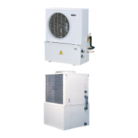
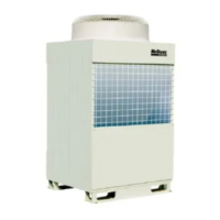
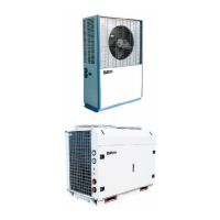
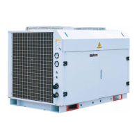
Air Cooled Mini Chiller
Models: MAC/M4AC 040-058A/AR
MAC 075-125B/BR
M4AC 040-058AE/ARE
M4AC 075-125BE/BRE

Questions and Answers:

McQuay MAC040A Specifications

General IconGeneral
BrandMcQuay
ModelMAC040A
CategoryChiller
LanguageEnglish

Summary

Nomenclature System

Features

General Specifications

Air-Cooler Condenser

Describes the construction and material of the air-cooled condenser coil.

Condenser Fan Motor

Details the high air flow propeller fan and its direct-drive motor.

Evaporator

Describes the heat exchanger construction and insulation.

Refrigerant Circuit

Details the factory-charged refrigerant circuit with expansion valves.

Additional Safety Protection

Outlines safety controls like high/low pressure switches and crank case heaters.

Antifreeze Protection

Explains activation of the antifreeze heater when water temperature drops.

Electronic Controller Settings

Provides steps for adjusting temperature settings via PCB and DIP switches.

Microprocessor Controller Functions

Details main functions like temperature control, defrosting, and alarm management.

User Interface and Alarms

Covers unit status LEDs, display, and alarm signaling actions.

Alarm Table

Lists display codes for various alarm conditions and their types.

Electrical Features

Details power supply range, fuse characteristics, and power driving specs.

Parameter Setting via Buttons

Explains how to set direct and user parameters using control buttons.

Factory Parameters and Operations

Covers factory settings, buzzer, defrosting, mode selection, and eeprom operations.

Specifications

Performance Characteristics

Technical Data

Evaporator Performance Data

Presents evaporator pressure drop and hydraulic lift data for various flow rates.

Glycol Correction Factors

Provides correction factors for capacity and pressure drop with glycol use.

Outlines and Dimensions

MAC040/050/058A/AR Dimensions

Shows dimensional drawings for MAC040/050/058A/AR models.

MAC075/100/125B/BR Dimensions

Provides dimensional drawings for MAC075/100/125B/BR models.

Compartment Dimensions

Details dimensions for the top and bottom compartments of the unit.

Wiring Diagrams

MAC040/050 A Cooling Wiring

Wiring diagram for MAC040/050 A models (Cooling Only).

MAC040/050/058AR Heat Pump Wiring

Wiring diagram for MAC040/050/058AR models (Heat Pump).

MAC075/100/125B Cooling Wiring

Wiring diagram for MAC075/100/125B models (Cooling Only).

MAC075/100/125BR Heat Pump Wiring

Wiring diagram for MAC075/100/125BR models (Heat Pump).

M4AC040/050/058AE Cooling Wiring

Wiring diagram for M4AC040/050/058AE models (Cooling Only).

M4AC040/050/058ARE Cooling Wiring

Wiring diagram for M4AC040/050/058ARE models (Cooling Only).

Special Precautions for R407C

R407C Refrigerant Properties

Explains R407C, its composition, ODP, and required lubricant.

Handling and Servicing Guidelines

Provides precautions for handling R407C, including leak checks and vacuuming.

Installation

Location for Installation

Requirements for selecting an installation location to ensure optimal cooling.

Installation Pipe Length

Guidelines on water connection pipe size and recommended maximum length.

Installation Site Considerations

Advice on supporting unit weight, avoiding dust/oil, and water source quality.

Installation Clearance

Clearance Requirements

Specifies required clearances around the unit for airflow and maintenance.

Servicing and Maintenance

Servicing Procedures

Describes routine checks, cleaning of air intake, and coil surface cleaning.

Maintenance Recommendations

Highlights regular maintenance for heat exchangers and water circuit filters.

Troubleshooting

General Troubleshooting

Covers common issues like compressor/fan failure and insufficient cooling.

Microprocessor Error Codes

Explains troubleshooting steps for specific PCB display codes (CO, PO, FL, HP, LP, E3).

Schematic Diagram

Cooling Version Schematic

Refrigerant and hydraulic circuit diagram for cooling models.

Heat Pump Version Schematic

Refrigerant and hydraulic circuit diagram for heat pump models.

Cooling Schematic (MAC075B-125B)

Schematic diagram for MAC075B to 125B cooling models.

Heat Pump Schematic (MAC075-125BR)

Schematic diagram for MAC075 to 125BR heat pump models.

Parts List and Exploded View

Top Compartment Parts

Exploded view and parts list for the top compartment of MAC/M4AC040-058A/AR.

Bottom Compartment Parts

Exploded view and parts list for the bottom compartment of MAC/M4AC040-058A/AR.

MAC/M4AC075-125B/BR Parts (View 1)

Exploded view and parts list for MAC/M4AC075-125B/BR units.

MAC/M4AC075-125B/BR Parts (View 2)

Second exploded view and parts list for MAC/M4AC075-125B/BR units.

MAC/M4AC075-125B/BR Parts (View 3)

Third exploded view and parts list for MAC/M4AC075-125B/BR units.

Related product manuals