EasyManua.ls Logo

McQuay M5ACV 030 CR

McQuay M5ACV 030 CR
99 pages
To Next Page IconTo Next Page
Loading...
M5ACV-2009
Air-Cooled Chiller
(R410A Inverter Series)
Models: M5ACV 030 CR
M5ACV 055 CR
M5ACV 075 CR
M5ACV 100 CR
M5ACV 135 CR
M5ACV 210 CR
Catalog
Question and Answer IconNeed help?

Do you have a question about the McQuay M5ACV 030 CR and is the answer not in the manual?

McQuay M5ACV 030 CR Specifications

General IconGeneral
BrandMcQuay
ModelM5ACV 030 CR
CategoryChiller
LanguageEnglish

Summary

Model Naming Convention

Model Code Breakdown

Explains the structure and meaning of the M5ACV model codes.

Key Features

Inverter Compressor Technology

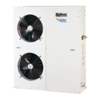
Details the advantages and operation of the inverter compressor system.

Safety Protection Features

Lists integrated safety features like pressure switches, sensors, and overload protectors.

Refrigerant Circuit Diagrams

Circuit Diagrams for M5 ACV Models

Illustrates the refrigerant flow and component layout for various M5ACV chiller models.

Control Panel Operation

Control Panel Safety and Installation

Outlines safety precautions and installation guidelines for the chiller control panel.

Control Panel Hardware Description

Unit Installation Guide

Control Panel Software Features

Control Panel Menu Structure

Main Menu and Operation Menu

Navigating the main menu to access operational settings like mode and temperature.

Settings, Timer, and Alarm Menus

Accessing advanced settings, scheduling, and alarm management features.

Operation and Settings Menus

Main and Operation Menus

Navigating main menu to adjust chiller operation modes and setpoints.

Advanced Parameter Settings

Set Parameter Groups

Accessing and modifying seven categories of advanced parameters.

General and Regulator Parameters

Configuring general settings and regulator parameters like setpoints.

Timer and Schedule Settings

Operation User Manual

Chiller Operation Control

Switching Modes and OnOff Control

Methods for changing chiller operational modes and power status.

Mode Set Temperature Adjustment

Adjusting Temperature via Operation Menu

Changing cooling and heating setpoints through the operation menu.

Advanced Temperature Settings

Modifying regulator parameters for temperature control in the settings menu.

Manual Defrost Operation

Parameter Settings Details

Panel Security: Password Change

Programmable Timer Schedule Setup

Alarm and Fault Record Management

Panel CMOS Reset

Troubleshooting Common Issues

Identifying Symptoms and Causes

Lists common unit problems, their possible causes, and troubleshooting steps.

Error Codes and Control Measures

A table detailing error codes, their descriptions, and the corresponding control responses.

R410 A Refrigerant Handling

Installation and Servicing Checklist

Critical checks and guidelines for installing and servicing R410A systems.

Dimensional Data: Installation Layouts

Installation Safety and Layouts

Pre-Installation Safety Warnings

Essential safety guidelines to follow before installing the unit.

Installation Cautions and Guidelines

Critical Installation Warnings

Safety cautions regarding flammable gas, drainage, overcharging, and panel closure.

Water Piping Connection Diagrams

Electrical Wiring and Safety Precautions

Fuse and Cable Size Recommendations

Table specifying recommended fuse ratings and cable sizes for different models.

Electrical Installation Cautions

Critical safety warnings for electrical wiring and connections.

General Safety and R410 A Cautions

Control Panel Operation Guide

Engineering and Physical Specifications

General Unit Specifications

Comprehensive data including capacity, power, dimensions, and weight.

Specifications: M5 ACV075 CR

General Data for M5 ACV075 CR

Detailed general specifications for the M5ACV075CR model.

Specifications: M5 ACV030055 CR

General Data for M5 ACV030 CR

Detailed general specifications for the M5ACV030CR model.

General Data for M5 ACV055 CR

Detailed general specifications for the M5ACV055CR model.

Specifications: M5 ACV100135 CR

General Data for M5 ACV100 CR

Detailed general specifications for the M5ACV100CR model.

General Data for M5 ACV135 CR

Detailed general specifications for the M5ACV135CR model.

Specifications: M5 ACV210 CR

General Data for M5 ACV210 CR

Detailed general specifications for the M5ACV210CR model.

Safety Device Details

Performance Data: M5 ACV075 CR

Performance Data: M5 ACV100135 CR Cooling

Performance Data: M5 ACV210 CR Cooling

Performance Data: M5 ACV030055 CR Heating

Performance Data: M5 ACV075 CR Heating

Performance Data: M5 ACV100135 CR Heating

Performance Data: M5 ACV210 CR Heating

Dimensional Data: M5 ACV030055 CR

Dimensional Data: M5 ACV100135 CR

Electrical Data: M5 ACV030055 CR

Electrical Data: M5 ACV100135 CR

Electrical Data: M5 ACV210 CR

Condenser Fan Motor and Compressor Data

Electrical specifications for fan motors and compressors.

Wiring Schematics

Servicing and Maintenance

Regular Maintenance Recommendations

Advice on routine maintenance for consistent performance and longevity.

Diagnostic Flowcharts

No Response After Power-On Diagnosis

Flowchart for troubleshooting units with no response after power-on.

Troubleshooting Flowchart Details

No Output Troubleshooting

Diagnostic flowchart for cases where the main board is functional but no output is generated.

Compressor Malfunction Troubleshooting

Diagnostic flowchart for issues where other functions work, but the compressor does not.

Flow and Voltage Protection Troubleshooting

Water Flow Error Diagnosis

Flowchart for troubleshooting water flow errors and related faults.

OverUnder Voltage Protection Diagnosis

Flowchart for diagnosing issues related to voltage protection.

Voltage and Pump Overload Troubleshooting

Under Voltage Protection Diagnosis

Flowchart for troubleshooting under voltage protection errors.

Pump Overload Diagnosis

Flowchart for diagnosing and resolving pump overload conditions.

Phase and Compressor Overload Troubleshooting

Phase Missing Diagnosis

Flowchart for troubleshooting phase missing errors.

Variable Compressor Overload Diagnosis

Flowchart for diagnosing Comp 1 overload issues.

Compressor Temp & Overload Troubleshooting

Discharge Overheat Diagnosis

Flowchart for troubleshooting Comp 1 discharge overheat.

Compressor Over-Current Diagnosis

Flowchart for diagnosing Comp 2 over-current faults.

Exploded Views and Parts Lists

Related product manuals