0 0 0 0 0 0 0 0 1 1 0 0 0 24
0 0 0 0 0 1 1 0 1 1 0 0 1 25
0 0 0 0 1 0 2 0 1 1 0 1 0 26
0 0 0 0 1 1 3 0 1 1 0 1 1 27
0 0 0 1 0 0 4 0 1 1 1 0 0 28
0 0 0 1 0 1 5 0 1 1 1 0 1 29
0 0 0 1 1 0 6 0 1 1 1 1 0 30
0 0 0 1 1 1 7 0 1 1 1 1 1 31
0 0 1 0 0 0 8 1 0 0 0 0 0 32
0 0 1 0 0 1 9 1 0 0 0 0 1 33
0 0 1 0 1 0 10 1 0 0 0 1 0 34
0 0 1 0 1 1 11 1 0 0 0 1 1 35
0 0 1 1 0 0 12 1 0 0 1 0 0 36
0 0 1 1 0 1 13 1 0 0 1 0 1 37
0 0 1 1 1 0 14 1 0 0 1 1 0 38
0 0 1 1 1 1 15 1 0 0 1 1 1 39
0 1 0 0 0 0 16 1 0 1 0 0 0 40
0 1 0 0 0 1 17 1 0 1 0 0 1 41
0 1 0 0 1 0 18 1 0 1 0 1 0 42
0 1 0 0 1 1 19 1 0 1 0 1 1 43
0 1 0 1 0 0 20 1 0 1 1 0 0 44
0 1 0 1 0 1 21 1 0 1 1 0 1 45
0 1 0 1 1 0 22 1 0 1 1 1 0 46
0 1 0 1 1 1 23 1 0 1 1 1 1 47
While setting the indoor address, there are a few rules need to follow. The rules are as follow:
a) Each indoor address must be unique and it must not duplicate within a system.
b) The first indoor address must be 0. Do not start the first indoor with address 1.
c) While setting the indoor address, the indoor address number cannot skip. For example, if
there are only 4 indoors in a system, the indoor address needs to be 0, 1, 2 and 3.
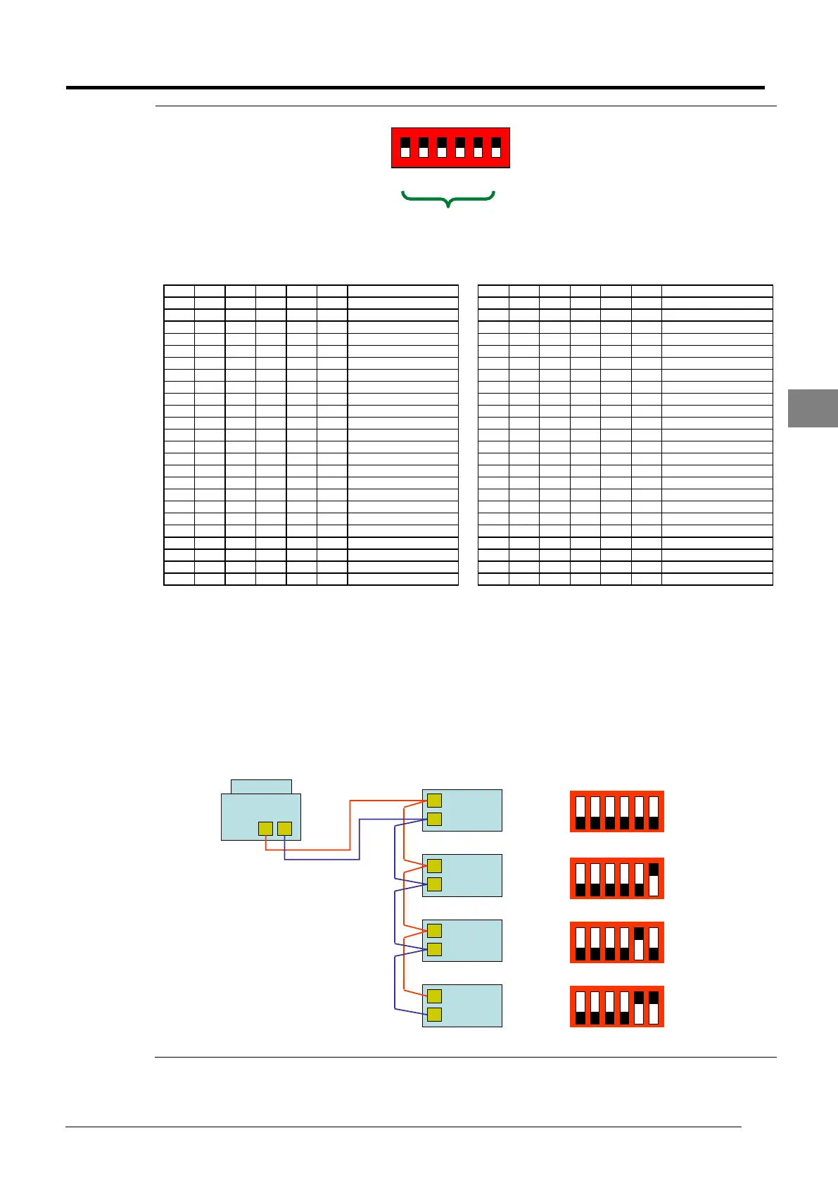
d) It is advisable that the indoor address follows the sequence of the communication wiring.
For example, for a 4 indoors in the system, the first indoor after the outdoor should have
address 0, the next indoor address should be 1 and the last indoor of the communication
wiring should be 3.
Example: