52 Service Manual SM-MDS_(ii)
5.6 Confirm Outdoor Dipswitch Setting
Similar to indoor, there are also some settings need to be done for outdoor unit. The unit capacity and model
type are usually set before ship out from the factory. However, it is advisable to check on the dipswitch again
before power up the outdoor. As for the outdoor address, it is only required when there is a series of outdoors
connected and control by the central control and monitoring software.
For outdoor model, there are two type of outdoor board:
MDOM PCB – For MDS-A series and 5MDS 50/60/70 B/BR
MDS-M PCB – (5)MDS 80-500 B/BR
5.6.1 Setting Up MDOM PCB
Basically, setting up MDOM PCB requires 3 steps:
1. Set up dipswitch 1 (J1)
2. Set up dipswitch 2 (J2)
3. Set up indoor quantity (K2 and K1 button)
0
For outdoor unit which runs on MDOM PCB, there are 2 set of dipswitches (J1 and J2). Besides
this, there is also a setting mode to modify certain important parameters (K2 and K1 button).
Please refer to page 14 for further description on their location.
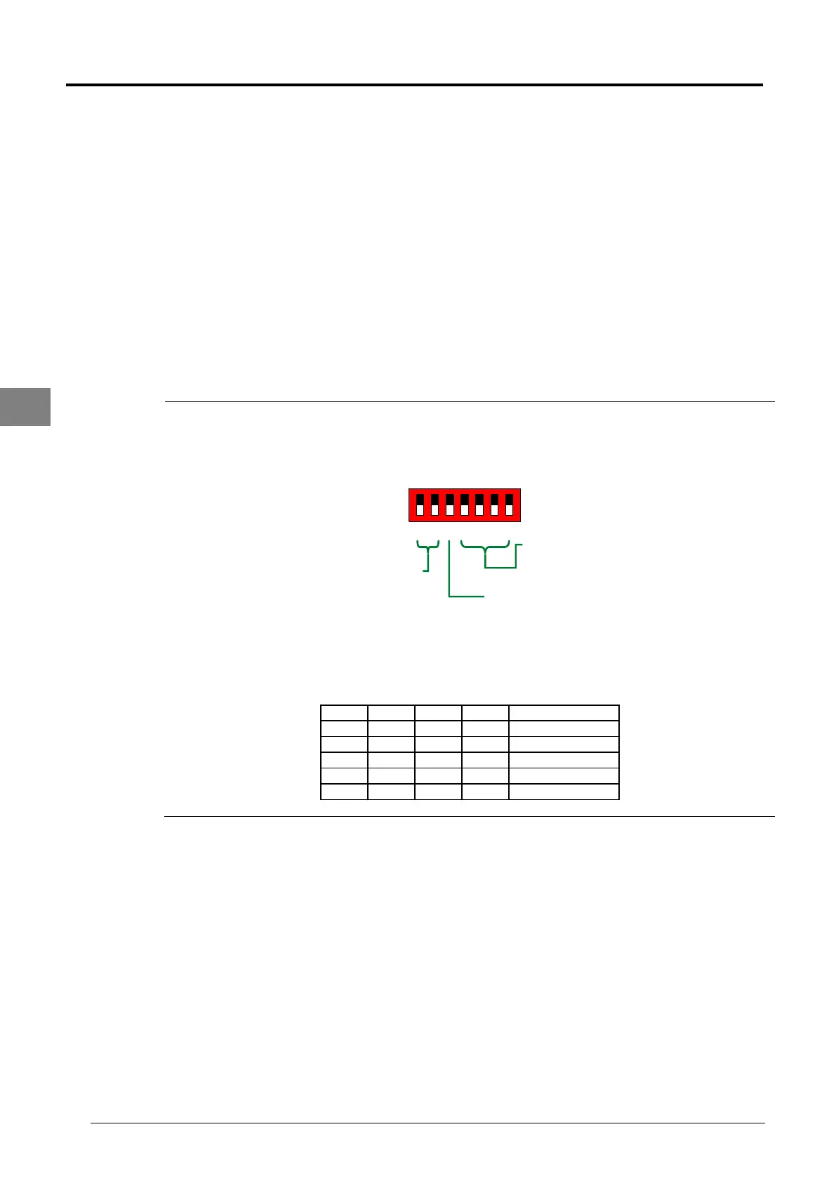
S1
ON (1)
OFF (0)
MDS A Capacity
Reserved
EXV Initial
Opening
1 2 3 4 5 6 7
For dipswitch 1 (J1), the main function is to determine the outdoor capacity. Dipswitch J1.1 and
J1.2 (EXV Initial Opening) is only use by R&D for testing purpose. During site commissioning, it
is advisable not to alter the setting unless advice by factory side. Dipswitch J1.3 is reserved for
future used. Dipswitch J1.4 to J1.7 is to determine the outdoor unit capacity.
J1.4 J1.5 J1.6 J1.7 Capacity
0 1 0 1 3HP
0 0 0 0 4HP
0 0 0 1 5HP
0 0 1 0 6HP
0 1 1 0 7HP