Do you have a question about the McQuay MDS Series and is the answer not in the manual?
Explains the use of digital scroll compressor technology and lists models.
Shows cooling and heating cycle operating ranges in Celsius.
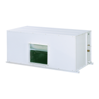
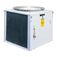
Illustrates the system components: outdoor unit, indoor unit, refnet, distributor, EXV box.
Table showing the maximum number of indoor units connectable per outdoor unit.
Details on maximum equivalent and actual piping lengths for R-22 and R-410A systems.
Lists refnet joints and distributors, and shows dimensions for specific models.
Lists indoor models with their respective EXV box models and pipe diameters.
Provides circuit diagrams for cooling and heating modes.
Covers sensor locations, EXV control, fan speed control, and anti-freeze protection.
Details on refnet/distributor connections, limitations, tilting angles, and orientations.
Explains the control algorithm for optional indoor heaters in heating or fan modes.
Step-by-step instructions for operating gas and liquid side ball valves during service.
Identifies MDOM and MDS-M PCBs, listing component locations and functions.
Identifies MC200-C and MC201-C PCBs, listing component locations and functions.
General information on wiring connections, communication protocols, and cable recommendations.
Details on connecting outdoor to indoor units via green terminal (Ain/Bin).
Wiring between multiple outdoor units, including jumper JP6 for the last unit.
Wiring for master/slave configurations, including terminal numbers.
Introduces types of handsets (wireless, wired, central) for controlling MDS indoor units.
Details on features and operations of the wireless handset G17.
Explains operations of the MC301 wired controller, including ON/OFF, temp setting, fan speed.
Details operations of MC303 central controller (Address Register, Mode Setting, Temp Setting).
Wiring diagram for Central Controller MC303 to indoor units via daisy chain.
Introduces Smart Commander software for commissioning and troubleshooting MDS systems.
Lists the minimum hardware requirements for running the Smart Commander software.
Step-by-step guide for installing the Smart Commander software.
Details wiring connections between outdoor units, gateway, and computer.
Guides users through setting up the Smart Commander software and connecting to the system.
Describes the Circuit Monitor and Server Monitor windows of the Smart Commander software.
Interface for monitoring all indoor and outdoor parameters, showing unit selection.
Interface for plotting system parameters as graphs, allowing parameter selection.
Details how to modify outdoor unit parameters and special operation orders.
Explains the importance of design drawings and reports for a smooth commissioning process.
Details checks for piping insulation, EXV box orientation before commissioning.
Explains methods for calculating and adding required refrigerant based on piping length.
Guides on checking indoor unit dipswitch settings for address, model, capacity, and function.
Details dipswitch settings for outdoor address, capacity, and model selection.
Explains dipswitch settings for indoor model and capacity identification.
Notes that Dipswitch 4 is reserved for software upgrades and should be OFF.
Instructions for powering up indoor units and activating auto-random restart function.
Guides on checking outdoor unit dipswitch settings for MDOM and MDS-M PCBs.
Steps for setting up MDOM PCB dipswitches (J1, J2) and indoor quantity.
Steps for setting up MDS-M PCB dipswitches (S1, S2, S3) for model, capacity, and indoor quantity.
Guides on powering up outdoor units and using Smart Commander for verification.
Instructions for starting all indoor units and performing outdoor/indoor checks.
Advises monitoring outdoor parameters after refrigerant addition and provides reference data.
Explains where error codes are displayed on indoor and outdoor units.
Lists error codes for decorative indoor units and their possible causes.
Lists indoor error codes displayed on MC301 controller and their causes.
Lists error codes for MDOM PCB outdoor units and their causes.
Lists error codes for MDS-M PCB outdoor units and their causes.
Flow chart for diagnosing indoor/outdoor sensor failures.
Flow chart for diagnosing outdoor pressure sensor errors.
Flow chart for diagnosing indoor pump errors.
Flow chart for diagnosing communication errors between units.
Flow chart for diagnosing compressor overload issues.
Flow chart for diagnosing high/low pressure switch trip errors.
Flow chart for diagnosing master/slave communication errors.
Flow chart for diagnosing general system malfunction errors.
Flow chart for diagnosing outdoor storage malfunction errors.
Flow chart for diagnosing indoor and controller communication errors.
Flow chart for diagnosing ambient temperature limit errors.
Flow chart for diagnosing wired controller storage problems.
Flow chart for diagnosing superheat protection value issues.
Flow chart for diagnosing emergency run conditions.
Flow charts for diagnosing hardware/software combination errors.
Flow chart for diagnosing PCB setting errors.
Charts showing compatibility between various indoor and outdoor PCBs.
Compatibility matrix for MC301 wired handset with different indoor PCBs.
Provides voltage and resistance values for high pressure sensors.
Provides voltage and resistance values for low pressure sensors.
Reference table for characters displayed on 7-segment LEDs for error codes.
Lists resistance values for temperature sensors (excluding TH1, TH8) at various temperatures.
Shows wiring and configuration details for 5MDS outdoor units on MDS-M PCB.
Reference data for R22 MDS-A series in cooling cycle for models 030 and 040.
Reference data for R22 MDS B series in cooling cycle for models 080.
Reference data for R22 MDS A series in heating cycle for models 030, 040, 050.
Reference data for R22 MDS B series in heating cycle for models 080 and 100.
Reference data for R410A MDS B series in cooling cycle for models 050 and 060.
Reference data for R410A MDS B series in heating cycle for models 050 and 060.
Reference data for R22 MDS BHC series cooling cycle for models 080/100/120BHC.
Illustrates refrigerant circuit diagrams for various MDS models.
Explains the key card access feature for indoor units and required components.
Shows LED indicators and actions for phase protector errors.
| Type | Scroll |
|---|---|
| Refrigerant | R-407C |
| Motor Type | Hermetic |
| Voltage Options | 208/230/460/575V |
| Frequency | 60 Hz |
| Weight | Varies with model |
| Stages | Single Stage |