OPERATING SEQUENCE
The single compressor
PEH/PHH
units can be operated as
individual units or in multiples as dictated by the system
design.
The compressor on-off sequencing is accomplished
through response to the Load Recycling Thermostat (LRT)
sensing the temperature of the chilled water leaving the
chiller.
The chiller will be started by the LRT approximately at the
design leaving chilled water temperature and will be
stopped at about 3°F below the control temperature.
While in operation, the chiller will be controlled by the Con-
trol Module, loading and unloading the compressor to main-
tain the desired chilled water temperature.
During all phases of operation, the critical functions of the
chiller are under constant surveillance by the safety controls.
Abnormal conditions will cause the chiller to be shut down
and usually will require some corrective action to prevent
recurrence. A set of panel lights on the control panel will in-
dicate the cause of shutdown. For the protection of the equip-
ment, the operator should determine the exact cause of shut-
down and correct the situation prior to operating the unit
again.
CONTROL SYSTEM
For the proper operation of the centrifugal chiller, a thorough
understanding of the control is essential.
The controls are housed for the most part in the Control
Center and in the Lube Box, both of which are mounted on
the chiller assembly.
A complete summary of the control components presented
in Table 1 identifies each control, its location and setting,
along with a brief description of its purpose in the control
scheme. Most of these controls are standard on all units while
a few may be special purpose or optional devices. Using this
chart in conjunction with the control diagram shipped with
the unit will aid in understanding the various control modes.
For the purpose of describing the controls, they have been
divided into two catagories Operating Controls and
Protective Controls and in each group, certain of the
important controls will be reviewed in some detail. There are
a dozen or so relays in the control center which respond to
another controlling device to open or close circuits. These
relays can be identified by the operator from the control
diagram.
OPERATING CONTROLS
The operating control group consists of devices which serve
specific functions in starting, operating and shutting down
the centrifugal compressor during normal operating condi-
tions. For this description it is assumed that the system con-
ditions monitored by the safety and protective controls are
normal and that those controls are positioned for running.
The ON-OFF switch on the control panel provides a means
of manual control to energize or de-energize the operating
circuit. When this switch is turned on, its self-contained light
will energize and the control circuit is ready for automatic
operation of the compressor.
The Load Recycling Thermostat (LRT) sensing leaving
chilled water temperature will cycle the compressor on the
line when the water temperature reaches the ON setpoint,
and will shut the compressor down when the water tempera-
ture drops to the OFF setpoint. The setting procedure is de-
tailed in the maintenance section of this manual.
To assure that the compressor will not be started too fre-
quently, the Time Delay Relay (TDR) will prohibit a restart
within 20 minutes of the last shutdown. This timing is for the
protection of the compressor motor and is not adjustable. It
is classified as an operating control because it functions as
a part of the starting sequence.
Once the TDR contacts close, the oil pump is started and
the Prelube Timer (PLT) is energized to assure oil pumping
and bearing lubrication for a fixed time prior to compressor
start, At the same time, the oil heaters which have been
energized during the compressor-off period are now shut off.
Simultaneous with starting the oil pump, the Oil Cooler
Solenoid (OCS) is energized, permitting coolant to flow
through the oil cooler to remove the heat generated by the
compressor bearings once the compressor starts.
Page 4
/
IM 307
At the end of the prelube period the control circuit is com-
pleted up to the Vane Closed switch (VC) which monitors the
position of the compressor capacity control vanes. This switch
permits compressor starting only when the vanes are in the
fully closed position.
To complete the control circuit for compressor starting, the
pump interlocks and water flow interlocks for the condenser
water and chilled water must be closed. Chilled water pumps
are normally operated continuously, whereas condenser
pumps may be cycled with the compressor. In this case the
Condenser Pump Cycling Relay (CWR) is energized and its
starter interlock contacts and condenser water flow switch
will complete the control circuit and the compressor will start.
Once the compressor is started, the Control Module func-
tions to load and unload the compressor in response to
changes in the leaving chilled water temperature. The Con-
trol Module will be discussed in greater detail in a later
section.
As the system load reduces and the Control Module
unloads the compressor to minimum capacity (about 10%
of full load), the compressor will continue to run, reducing
the water temperature until the LRT shuts off the machine
when the water temperature drops to the OFF setpoint.
The control panel has two lights which indicate the status
of control. The COMP RUN light shows that the compressor
is running under normal control and the LOAD RECYCLE
light indicates the compressor has been taken off line by a
normal operating control and is waiting for a restart signal.
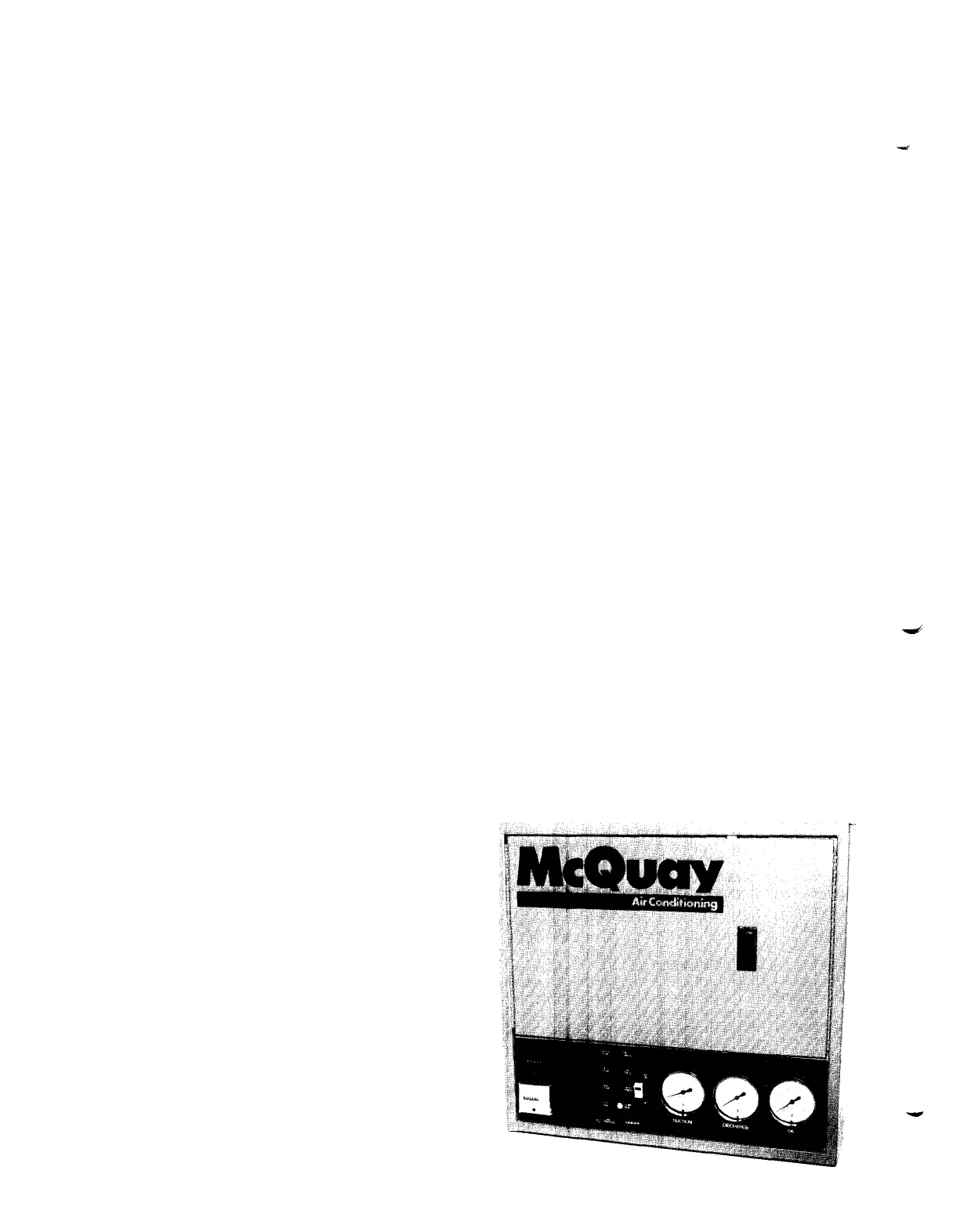
FIGURE 2. CONTROL CENTER
 Loading...