McQuay IM 987 61
Wiring Diagrams
TR1, 2 Transducer, pressure Main control box
UV Ultra-violet light(s) Coil/discharge section
VM1 Valve motor #1, heating Gas heat box/ heat section
VM5 Valve motor #5, cooling Coil section, cool
VV1 Vent valve, gas heat Heat Section, Gas
ZNT1 Zone temp. sensor, setback Field installed
ID Description Standard location
200/ H200
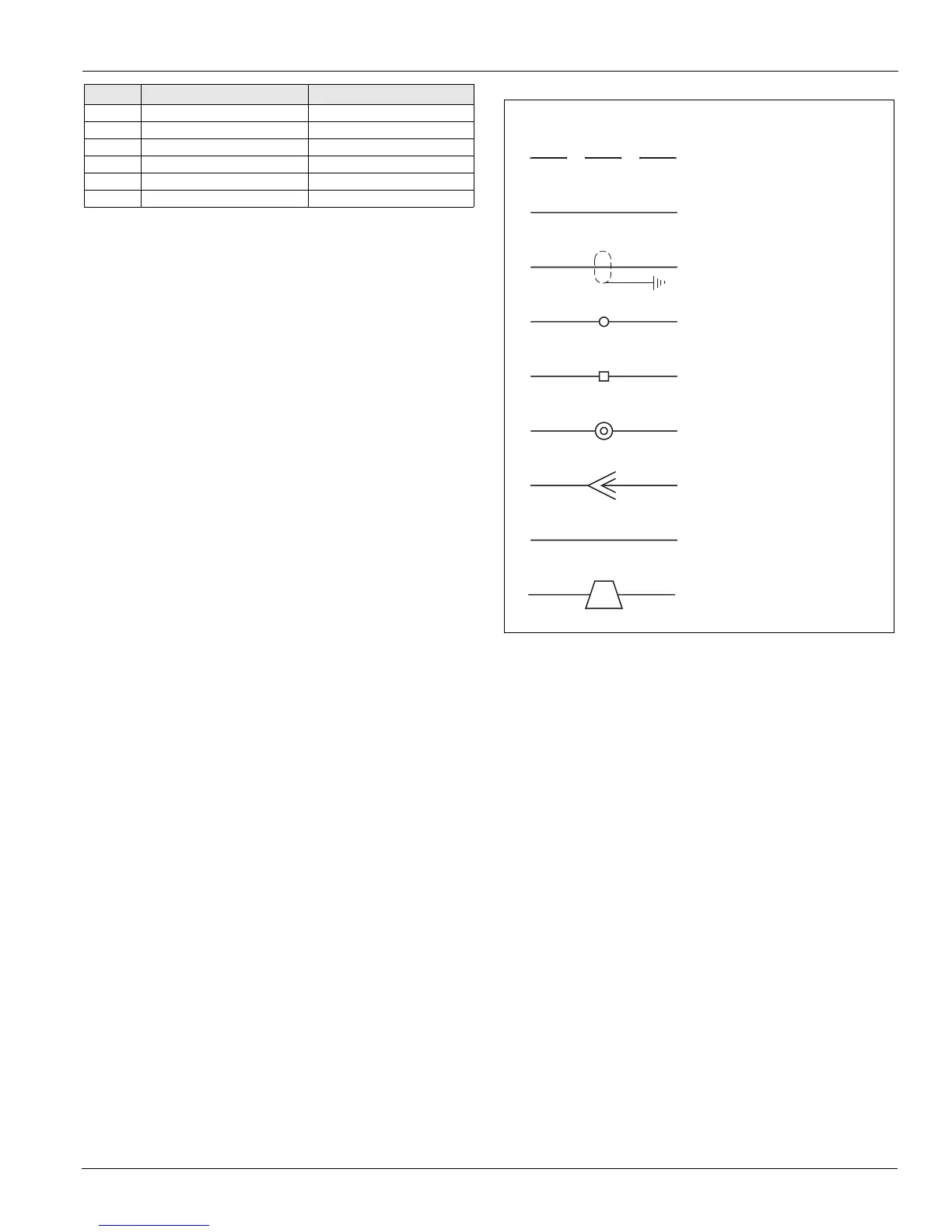
1. Field wiring
3. Shielded wire/cable
4. Main control box
terminals
5. Auxilliary box
terminals
6. Field terminals
7. Plug connector
8. Wire/harness number
General Notes
2. Factory wiring
9. Wire nut/ID
WN7
 Loading...