EasyManua.ls Logo

McQuay RCS User Manual

McQuay RCS
100 pages
To Next Page IconTo Next Page
Page #1 background imageLoading...
Page #1 background image
IM-738 Page 1
Installation and Maintenance Manual IM-738
Group: Applied Systems
Part Number: IM-738
Date: April 2002
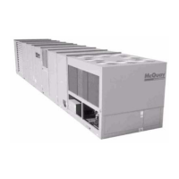
RoofPak
®
Singlezone Roof Mounted
Heating and Cooling Units with Scroll Compressors
RPS/RDT/RFS/RCS 015-075C
© 2002 McQuay International

Table of Contents

Question and Answer IconNeed help?

Do you have a question about the McQuay RCS and is the answer not in the manual?

McQuay RCS Specifications

General IconGeneral
Heating CapacityUp to 500 MBH
ConstructionGalvanized steel with thermal break
Coil OptionsChilled water, hot water, steam, DX
Filter Optionsbag, pleated
Voltage208/230V, 460V, 575V
DimensionsVaries with unit size and configuration
WeightVaries with unit size and configuration

Summary

Introduction

Hazard Identification Information

Provides warnings and cautions for safe installation and operation.

Controls, Settings, and Functions

Mechanical Installation

Unit Clearances

Specifies required clearances for service access and proper unit ventilation.

Ventilation Clearance

Overhead Clearance

Details restrictions for overhead obstructions above the unit's condenser and air handler sections.

Post and Rail Mounting

Rigging and Handling

Instructions and precautions for safely lifting and handling the unit.

Reassembly of Split Units

RPS Factory Split at Condenser

Phase 2. Reconnecting Refrigerant Piping

Procedures for reconnecting refrigerant lines after unit section reassembly.

Reconnecting Power and Control Wiring

RPS/RDT Factory Split at Fan

Phase 1. Setting the Sections and Cabinet Reassembly

Steps for positioning and mechanically joining the unit sections after fan split.

Phase 2. Reconnecting Power and Control Wiring

Procedures for reconnecting electrical wiring after fan split reassembly.

Piping Recommendations

Leak Testing

Methods for testing the system for refrigerant leaks and pressure integrity.

Evacuation

Steps for evacuating the refrigerant system to remove air and moisture.

Refrigeration Service Valves

Charging the System

Step-by-step instructions for charging the refrigerant system.

Damper Assemblies

Economizer Dampers

Information on economizer damper operation, adjustment, and linkage.

Electrical Installation

Field Power Wiring

Requirements and procedures for field power wiring, including compliance with codes.

Fan Trol

Field Control Wiring

Preparing Unit for Operation

Sequences of Operation

Fan Operation

How the supply and return fans operate and are controlled.

Economizer Operation

How the economizer functions based on enthalpy and outdoor air conditions.

Mechanical Cooling Operation

4-Compressor/4 Stage Unit

Specific operational details for units with four compressors and four cooling stages.

Heating

Gas Furnace, Modulating Burner (3 to 1 turn down)

Sequence of operation for modulating gas furnaces.

Wiring Diagrams

Typical Power Circuit Wiring (6 Compressor Arrangement with VFD Shown)

Typical Main Circuit Wiring (with Inlet Vane and Controls by Others)

Typical Main Circuit Wiring (with VFD and Controls by Others)

Typical Condensing Unit Control for RPS with MicroTech II Control (4 Compressor Unit Shown. RCS Has Minor Variations)

Typical Condensing Unit Control with Control Schematic for RPS (Controls by Others, 6 Compressor Unit Shown, RCS Has Minor Variations)

Typical Gas Furnace Control Circuit (Modulating Burner, Mixed Air Intake)

Propeller Exhaust Fan Control

Check, Test, and Start Procedures

Before Start-up

Initial checks and preparations required before powering up the unit.

Power-up

Sequence of events when the unit is first powered on.

Economizer Start-up

Compressor Start-up

Expansion Valve Superheat Adjustment

Heating System Start-up

Rooftop Equipment Warranty Registration Form:

INITIAL CHECK

Checklist of initial inspections and verifications before unit start-up.

FAN DATA

Section for recording supply and return fan operational data.

START-UP COMPRESSOR OPERATION

Procedures for verifying compressor start-up and operation.

Warranty Registration Form (continued)

PERFORMANCE DATA

Recording of compressor voltages, amperages, and operating pressures.

GAS & OIL BURNER CHECK, TEST & START

Procedures for checking and testing gas and oil burner components.

QUALITY ASSURANCE SURVEY REPORT

Survey questions to assess product quality, installation, and serviceability.

ELECTRIC HEAT CHECK, TEST & START

Steps for verifying electric heat system operation and electrical connections.

GAS BURNER CHECK, TEST & START

Specific tests and checks for the gas burner system.

Final Control Settings

Maintenance

Preventive Maintenance

Recommended routine maintenance tasks to ensure reliability and avoid issues.

Refrigerant Charge

Service and Warranty Procedure

Limited Product Warranty (North America)

Related product manuals