Page 6 IM-738
Condenser Fan Arrangement
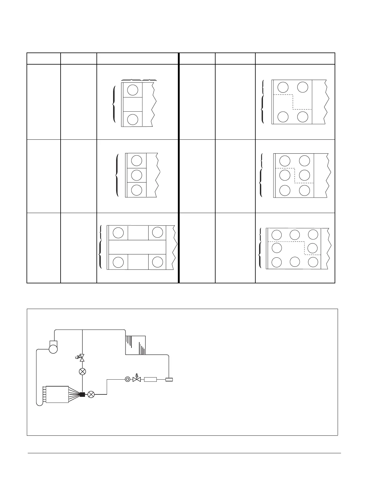
Table 2 shows the condenser fan numbering conventions and locations for each unit size.
Table 2: Condenser Fan Arrangement
Refrigerant Circuit Schematic
Figure 3. Circuit Schematic
UNIT SIZE
REFRIGERANT
CIRCUIT
ARRANGEMENT UNIT SIZE
REFRIGERANT
CIRCUIT
ARRANGEMENT
015C
018C
020C
1 or 2
045C
050C
1
2
025C
030C
1 or 2
060C
070C
1
2
036C
040C
1
2
075C
1
2
C O N D
A H U
5 1 . 5 "
1 3 0 8 m m
1 1
1 2
8 3 "
2 1 0 8 m m
1 1
1 2
2 1
2 2
1 1
1 2
1 3
5 1 . 5 " ( 1 3 0 8 m m )
1 1
1 2
2 1
2 2
2 3
1 3
8 3 " ( 2 1 0 8 m m )
1 0 0 " ( 2 5 4 0 m m )
1 1
2 1
1 2
2 2
1 1 9 " ( 3 0 2 2 m m )
1 1
2 1
1 3
2 3
1 2
2 2
2 4
1 4
B
A
J
D
L
K
N
O
M
C
H G F
I
E
A Compressor †
B Discharge Line †
C Condenser Coil †
D Evaporator Coil*
E Manual Shutoff Valve†
F Filter-Drier*
G Liquid Line Solenoid Valve*
H Sightglass*
I Liquid Line*†
J Suction Line
K Thermal Expansion Valve*
L Distributor*
M Hot Gas Bypass Solenoid Valve (optional)*
N Hot Gas Bypass Lines (optional)* †
O Hot Gas Bypass Valve (optional)*
*Supplied on RFS units †Supplied on RCS units