Page 12 IM-738
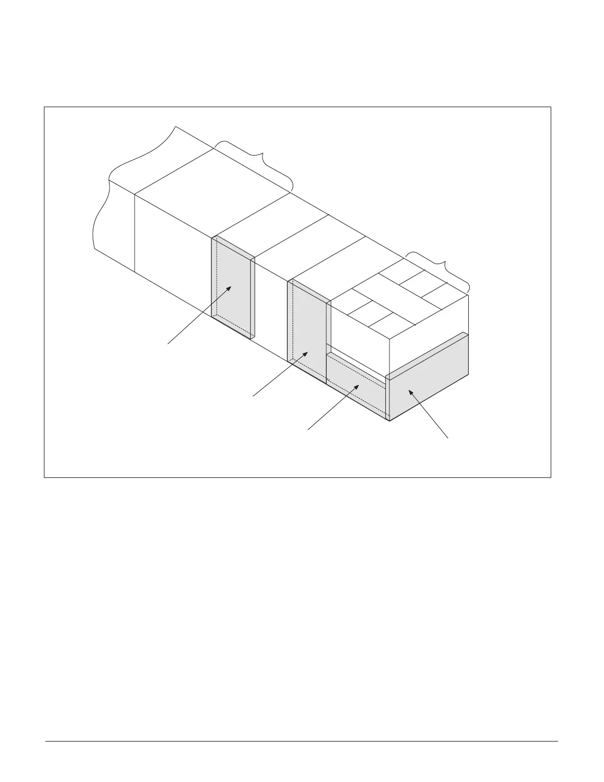
Control Panel Locations
The unit control panels and their locations are shown in the
following figures. These figures show a typical unit configura-
tion. Specific unit configurations may differ slightly from
these figures depending on the particular unit options. See
“Wiring Diagrams” on page 54 for the Legend and compo-
nent description.
Figure 9. Control Panel Locations
C o n d e n s e r C o n t r o l
P a n e l ( 0 3 6 - 0 7 5 )
C o n d e n s e r C o n t r o l
P a n e l ( 0 1 5 - 0 3 0 )
M a i n C o n t r o l P a n e l
E l e c t r i c H e a t
C o n t r o l P a n e l
( O p t i o n a l )
S u p p l y F a n
S e c t i o n
C o n d e n s e r
S e c t i o n