Page 38 IM-738
Subcooling
When field charging the unit, the following must be followed
to properly charge the unit:
• All compressors on each circuit operating at full capacity.
• Allowable subcooling ranges are between 13°F to 20°F.
• Ambient temperature must be between 60°F and 105°F.
• Hot Gas Bypass NOT operating (only if unit is supplied with option)
• SpeedTrol motors operating at 100%
(only if unit is supplied with option)
If any one of the above items is not followed, subcooling read-
ings will not be accurate and the potential exists for over or
undercharging of the refrigerant circuit.
Condensate Drain Connection
The unit is provided with a 1.5" male NPT condensate drain
connection. Refer to certified drawings for the exact location.
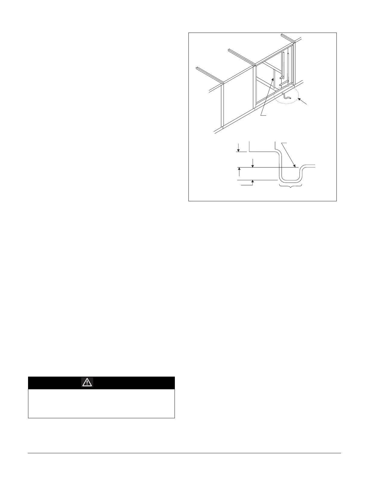
The unit and drain pan must be level side to side and a P-trap
must be installed for proper drainage.
RPS units may have positive or negative pressure sections. It is
recommended that traps be used in both cases with care given
to negative pressure sections. In Figure 42, dimension "A"
should be a minimum of 8" (203 mm). As a conservative mea-
sure to prevent the cabinet static pressure from blowing or
drawing the water out of the trap and causing air leakage,
dimension A should be two times the maximum static pressure
encountered in the coil section in inches w.c.
Drainage of condensate directly onto the roof may be accept-
able; refer to local codes. It is recommended that a small drip
pad of either stone, mortar, wood or metal be provided to pro-
tect the roof against possible damage.
If condensate is to be piped into the building drainage system,
the drain line should be pitched away from the unit at a mini-
mum of 1/8" per foot. The drain line must penetrate the roof
external to the unit. Refer to local codes for additional require-
ments. Sealed drain lines require venting to provide proper
condensate flow.
Where the cooling coils have intermediate condensate pans on the
face of the evaporator coil, copper tubes near both ends of the coil
provide drainage to the main drain pan. Check that the copper
tubes are in place and open before the unit is put into operation.
Because drain pans in any air conditioning unit will have some
moisture in them, algae, etc. will grow. Periodic cleaning is
necessary to prevent this buildup from plugging the drain and
causing the drain pan to overflow. Also, the drain pans should
be kept clean to prevent the spread of disease. Cleaning should
be performed by qualified personnel.
Figure 42. Condensate drain connection
Unit Piping
Gas Piping
See the "Installation" section of the gas-fired furnace installa-
tion manual, Bulletin No. IM 684 or 685.
Fuel Oil Piping
See the "Installation" section of the forced draft oil-fired fur-
nace installation manual, Bulletin No. IM 198.
Hot Water Coil Piping
Hot water coils are provided without valves for field piping
or piped with three-way valves and actuator motors. Note: If
the unit is equipped with an iron valve, connecting to a cop-
per piping system will likely cause galvanic corrosion to
occur and the valve will not last. All coils have vents and
drains factory installed.
Hot water coils are not normally recommended for use with
entering air temperatures below 40°F (4°C). No control system
can guarantee a 100% safeguard against coil freeze-up. Glycol
solutions or brines are the only freeze-safe media for operation
of water coils at low entering air temperature conditions.
When no factory piping or valve is included, the coil connec-
tions are 1 5/8" ODM copper. With the factory piping and valve
package, field piping connections are the same NPT size as the
valve with female threading (see Figure 43 on page 39).
Refer to the certified drawings for the recommended piping
entrance locations. All piping penetrations must be sealed to
prevent air and water leakage.
Note: The valve actuator spring returns to a stem down
position upon power failure. This allows full flow
through the coil.
WARNING
Material that can grow in drain pans should be
cleaned on periodically. Material in uncleaned drain
pans may cause disease.
Cleaning should be performed by qualified personnel.
S t a t i c P r e s s u r e " P "
( i n . w . o . )
D r a i n P a n
4 " ( 1 0 2 m m )
M i n i m u m
" A "
8 " ( 2 0 3 m m )
M i n . o r 2 x " P "
M i n i m i z e T h i s
D i m e n s i o n
N o t e : D r a i n l i n e m u s t
n o t b e r u n h i g h e r
t h a n t h i s l e v e l
C o p p e r T u b e
( o n e e a c h e n d o f c o i l )
S e e V i e w " A "