Page 10 IM-738
Control Locations
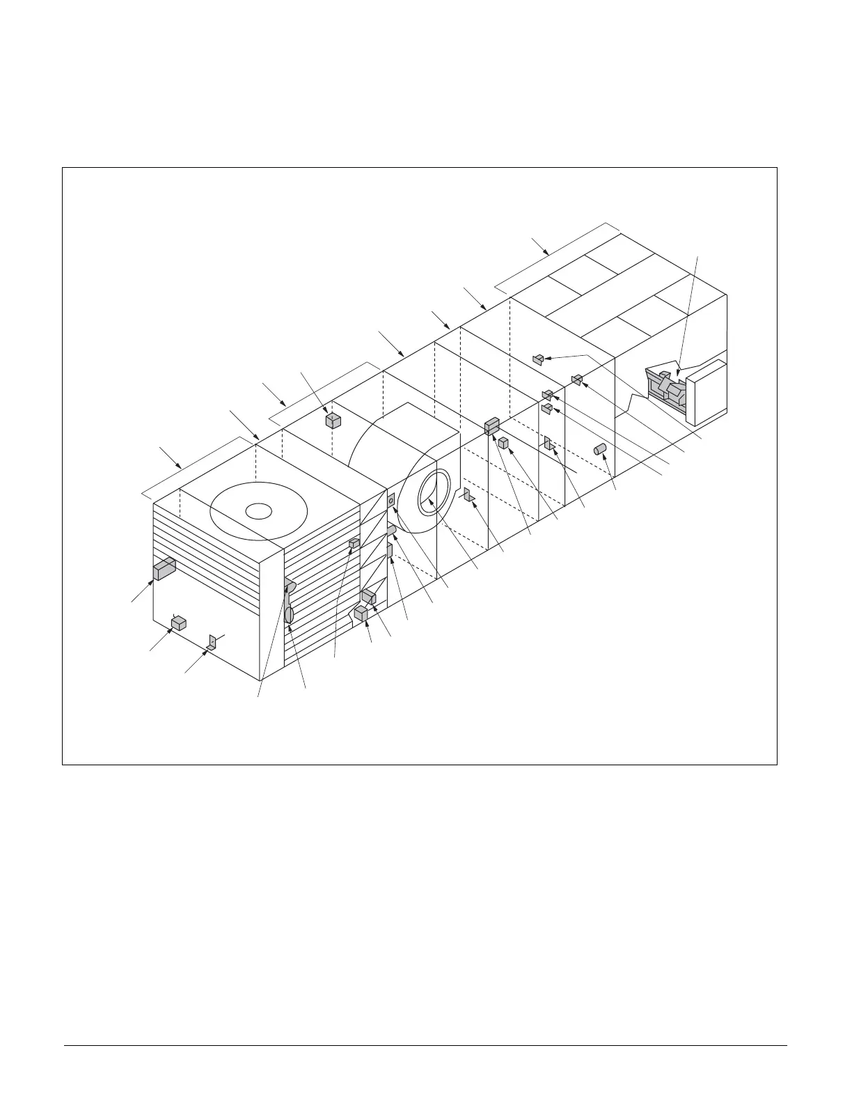
Figure 7 (RPS Units) and Figure 8 on page 11 (RDT Units)
show the locations of the various control components mounted
throughout the units. See “Control Panel Locations” on page
12 for the locations of control components mounted in control
panels. Additional information is included in Table 3 on
page 18 and the wiring diagram legend which is included in
“Wiring Diagrams” on page 54.
Figure 7. Control Locations - RPS Units
R e t u r n A i r
E c o n o m i z e r
F i l t e r
S e c t i o n
S u p p l y
F a n
S e c t i o n
A C 1
( O p t i o n a l )
H e a t
S e c t i o n
D X
S e c t i o n
D i s c h a r g e
P l e n u m
S e c t i o n
C o n d e n s o r
S e c t i o n
A C 1
( O p t i o n a l )
S D 2
( O p t i o n a l )
R A T
L T 1 1
( O p t i o n a l )
S 1 1 , R E C 1 1
O E A
A C T 3
P C 5
S 1 0 , R E C 1 0 ( O p t i o n a l )
L T 1 0 ( O p t i o n a l )
H L 2 2 ( O p t i o n a l )
P C 7
E A T
S D 1 ( O p t i o n a l )
V M 1 ( O p t i o n a l )
D A T
C A T
S V 6 ( O p t i o n a l )
S V 5 ( O p t i o n a l )
S V 1
S V 2
H P 1 - 2
L P 1 - 2
H T R 1 - 2