IM-738 Page 37
Refrigeration Service Valves
The unit is shipped with all refrigeration service valves
closed. RDT, RPS and RCS units have the following:
Discharge Valve - One per refrigerant circuit, located between
the compressors and condenser.
Liquid Valve - One per refrigeration circuit, located at end of
condensing section opposite the condenser control box.
RFS units do not ship with service valves installed. Before
attempting to start the compressors, all refrigeration service
valves should be fully opened and backseated.
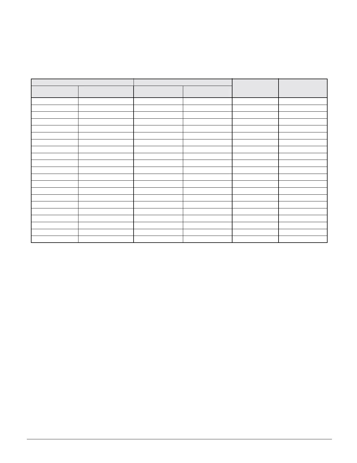
Table 13: Pressure-vacuum equivalents
Charging the System
RCS units are leak tested at the factory and shipped with a
nitrogen holding charge. If the holding charge has been lost
due to shipping damage, the system should be charged with
enough refrigerant to raise the unit pressure to 30 psig after
first repairing the leaks and evacuating the system.
1. After all refrigerant piping is complete and the system has
been evacuated, it can be charged as described in the para-
graphs following. Connect the refrigerant drum to the
gauge port on the liquid shutoff valve, and purge the
charging line between the refrigerant cylinder and the
valve. Then open the valve to the midposition.
2. If the system is under a vacuum, stand the refrigerant
drum with the connection up, open the drum and break the
vacuum with refrigerant gas.
3. With a system gas pressure higher than the equivalent of a
freezing temperature, invert the charging cylinder and ele-
vate the drum above the condenser. With the drum in this
position and the valves open, liquid refrigerant will flow
into the condenser. Approximately 75% of the total require-
ment estimated for the unit can be charged in this manner.
4. After 75% of the required charge has entered the con-
denser, reconnect the refrigerant drum and charging line
to the suction side of the system. Again purge the connect-
ing line, stand the drum with the connection side up, and
place the service valve in the open position.
Important: At this point, the charging procedure should be
interrupted and prestart checks made before
attempting to complete the refrigerant charge.
Note: It is recommended that the total operating charge per cir-
cuit be stamped on the unit nameplate for future reference.
Refrigerant Charge
Each unit is designed for use with R-22. The total charge per
circuit is the sum of four values. The exact charge for a one
piece RPS/RDT is on the unit nameplate.
1. Condenser section charge - refer to Table 10 on page 36.
2. Evaporator coil charge - refer to Table 10 on page 36.
3. Charge for length of unit piping to the evaporator coil -
refer to Table 10 on page 36.
4. Charge for length of interconnecting piping between the
RCS and RFS units, installed by field - refer to Table 12
on page 36.
Note: The values shown in Table 10 and Table 12 are for
each circuit.
Note: The total operating charge per circuit should not exceed
the pumpdown capacity per circuit, shown in Table 10.
ABSOLUTE PRESSURE ABOVE ZERO VACUUM BELOW 1 ATMOSPHERE APPROXIMATE
FRACTION OF
1 ATMOSPHERE
BOILING POINT
OF H2O AT EACH
PRESSURE (
o
F)
MICRONS PSIA
MERCURY
(MM)
MERCURY
(IN.)
0 0 760.00 29.921 — —
50 0.001 759.95 29,920 1/15,200 —50
100 0.002 759.90 29.920 1/7,600 -40
150 0.003 759.85 29.920 1/5,100 —33
200 0.004 759.80 29.910 1/3,800 —28
300 0.006 759.70 29.910 1/2,500 —21
500 0.009 759.50 29.900 1/1,520 —12
1,000 0.019 759.00 29.880 1/760 1
2000 0.039 758.00 29.840 1/380 15
4,000 0.078 756.00 29.760 1/189 29
6000 0.117 754.00 29.690 1/127 39
8,000 0.156 752.00 29.600 1/95 46
10,000 0.193 750.00 29.530 1/76 52
15,000 0.290 745.00 29.330 1/50 63
20,000 0.387 740.00 29.130 1/38 72
30,000 0.580 730.00 28.740 1/25 84
50,000 0.967 710.00 27.950 1/15 101
100,000 1.930 660.00 25.980 2/15 125
200,000 3.870 560.00 22.050 1/4 152
500,000 9.670 260.00 10.240 2/3 192
760,000 14.697 0 0 1 Atmosphere 212