Page 4 IM-738
Unit Description
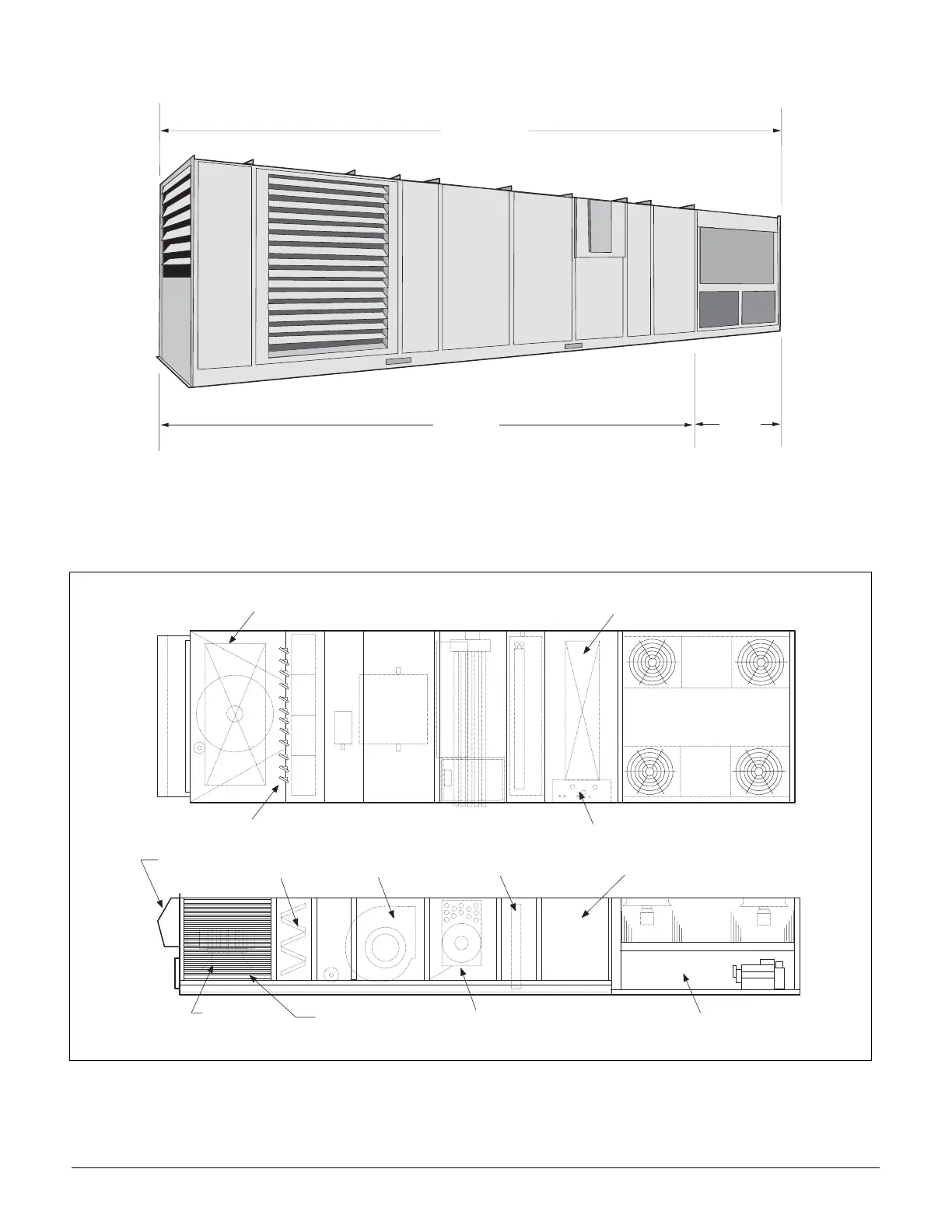
Typical Component Locations
Figure 1 shows a typical RPS unit with the locations of the
major components. Figure 2 on page 5 shows a typical RDT
unit with the locations of the major components. These figures
are for reference only. See the certified submittals for actual
specific dimensions.
Figure 1. Typical Component Locations - RPS Units
R P S / R D T
R F S
R C S
E v a p o r a t o r C o i l
P o w e r & C o n t r o l E n t r a n c e s
D i s c h a r g e P l e n u m
( M a i n C o n t r o l P a n e l )
A i r C o o l e d C o n d e n s e r
H e a t S e c t i o n ( N a t u r a l G a s , O i l ,
S t e a m , H o t W a t e r , E l e c t r i c )
S u p p l y A i r F a n
F i l t e r S e c t i o n
E x h a u s t
H o o d
R e t u r n A i r
F a n
O u t s i d e A i r
L o u v e r s
B o t t o m R e t u r n A i r O p e n i n g
B o t t o m D i s c h a r g e A i r O p e n i n g
O u t s i d e & R e t u r n A i r D a m p e r s