IM-738 Page 47
Field Control Wiring
Roof Pak applied rooftop units are available with several con-
trol arrangements which may require low voltage field wiring.
Detailed descriptions of various field control wiring options
and requirements are included in the "Field Wiring" section of
Bulletin No. IM 696, "MicroTech II Applied Rooftop Unit
Controller." Refer to the unit wiring diagrams for additional
installation information.
Wiring must comply with applicable codes and ordinances.
The warranty is voided if wiring is not in accordance with
these specifications.
RPS,RDT and RFS Units
Most field control wiring connections are made at terminal
block TB2, which is located in the main control panel. Some
control options require field wiring connections to terminal
block TB7, which is also located in the main control panel.
Refer to Figure 57 and see “Control Panel Locations” on
page 12. Two 7/8" knockouts are provided for wire entry.
RFS/RCS Units
The RCS unit receives 115V and 24V control circuit power
and a number of control signals from the RFS unit. Two 7/8"
knockouts are provided in the right side of the RCS control
box. The 115V wiring is connected to terminal block TB3
through the upper knockout. The 24V wiring is connected to
terminal block TB2 through the lower knockout.
Interconnecting wiring enters the RFS unit through 7/8"
knockouts in the bottom of the main control panel. The 115V
wiring is connected to TB5 and 24V wiring is connected to ter-
minal block TB7. Refer to Figure 58.
A 7/8" knockout is also available in the end of the unit base as
shown in Figure 58.
Note: If a single conduit containing 24V and 115V wiring
is run above the roofline between the RFS and RCS
units, the 24V wiring must be reinstalled as an NEC
Class I wiring system.
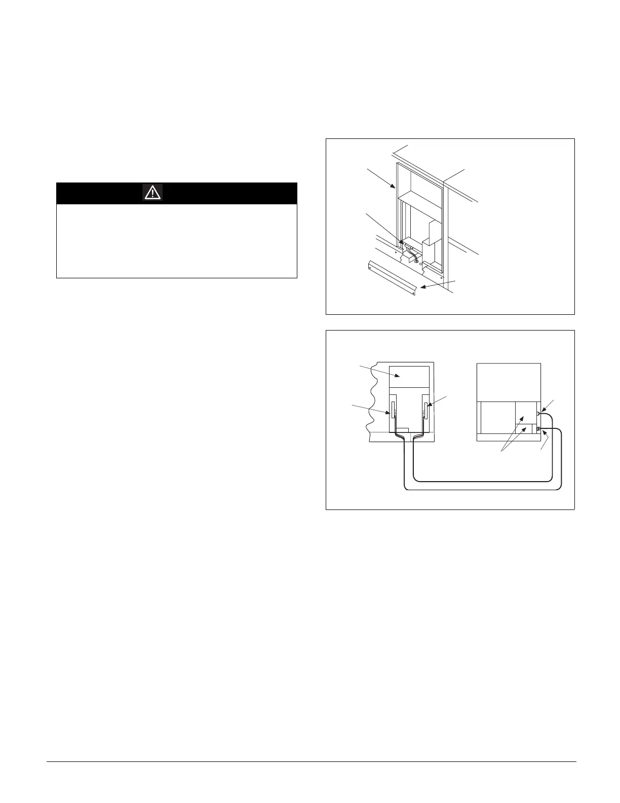
Figure 57. RDT, RFS, RPS Field Control Wiring Connections
Figure 58. RFS and RPS Interconnecting Control Wiring
WARNING
Electrical shock hazard.
Can cause severe injury or death.
Connect only low voltage NEC Class II circuits to
terminal blocks TB2 and TB7.
Reinstall and secure all protective deadfront panels
when the wiring installation is complete.
M a i n C o n t r o l
P a n e l
2 4 V F i e l d
T e r m i n a l
B l o c k
( T B 2 )
C o n t r o l W i r i n g R a c e w a y
C o v e r ( R e m o v e f o r a c c e s s
t o h a r n e s s f r o m m a i n c o n t r o l
b o x t o u n i t m o u n t e d
c o n t r o l d e v i c e s )
M a i n
C o n t r o l
P a n e l
T B 7
( 2 4 V )
T B 5
( 1 1 5 V )
C o n d e n s e r
C o n t r o l P a n e l s
R F S U n i t
R C S U n i t
T B 3
( 1 1 5 V )
T B 2
( 2 4 V )