IM 812 / Page 18 of 24
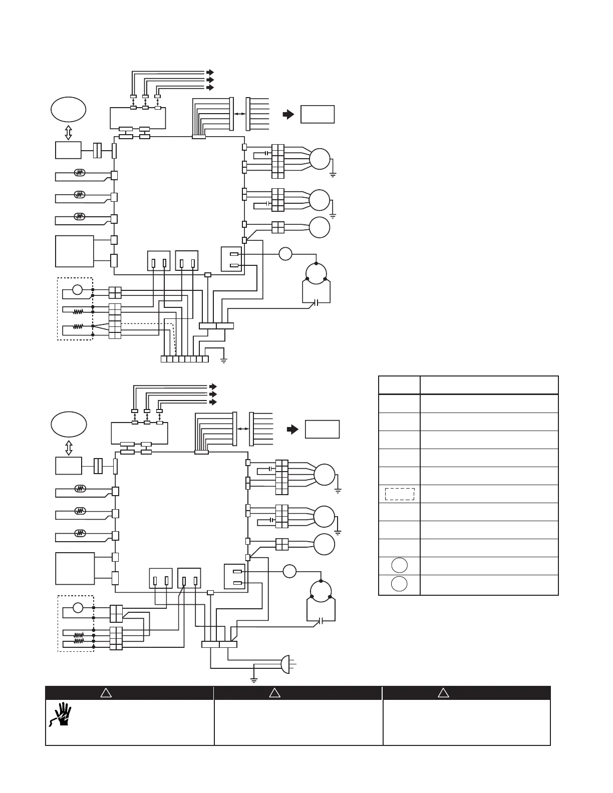
Wiring Diagrams – PTAC/HP - 07B/09B/12B
Figure 17. Universal Heater with Field Installed Power Cord
Figure 18. Fixed Heater with Factory Installed Power Cord
Disconnect all electrical power before servicing
unit to prevent injury or death due to electrical
shock.
Hazardous Voltage!
Disconnect all electric power including remote
disconnects before servicing. Failure to disconnect power
before servicing can cause severe personal injury
or death.
Use copper conductors only. Unit terminals are not
designed to accept other types of conductors.
Failure to do so may cause damage to the
equipment.
WARNING
!
CAUTION
!
DANGER
!
NOTE: * H1 Heater terminal is always 0.25" with
black shrink sleeve.
H2 Heater terminal will be either 0.188"
with black sleeve or 0.25" with clear or red
sleeve or green mark on sleeve.
** Only for Heat Pump (PTHP)
Symbol Name
PC1 Main PC Board
PC2 Dip Switch PC Board
CM Compressor Motor
OM Outdoor Motor
IM Indoor Motor
Component Provided as Assembly
SC Reversing Valve Solenoid Coil
T# Terminal Block
P# Connector
OLP
Overload Protector
HL
Heater High Limit
Motion Sensor
Door Sensor
Remote ON/OFF Dry Contacts
BW
WH
YL
BU
GN
BK
RD
BW
WH
YL
BU
GN
BK
RD
BK
BU
RD
BW
OR
OR
BW
BK
BU
RD
CAP
CAP
BK
BU
RD
RD
BU
BK
WH
WH
P6
P5
P7
WH
WH
BK
BK
BK
BK
BK
BK
RD
CAP
SC**
OM
CM
IM
N
Hi
Lo
N
Hi
C
R
S
BU
RD
N
T1
L
BK
RD
RD
RD
WH
WH
BW
BW
WH
WH
BW
BW
PC1
NEUTRAL 2
HIGH FAN
LOW FAN
NEUTRAL 3
OTFAN HI
4WV
NEUTRAL 1
RL6
L
C
C
NO NO
RL8
RL7
L COMP
P3
P2
RD
RD
H1
H2
Electric Heater*
Transformer
Control
Pad
Wireless
Remote
Control
Room
ID Coil
OD Coil**
OutCoil
InCoil
Room
CN8
PRI
SEC
CN11
CN5
CN2
CN10 CN6
CN7
CN4 CN3
PC2
BK
BK
BK
BK
GY
GY
THERMISTOR
HL
1
1
2
2
4
4
1
1
3
3
6
6
1
1
2
2
3
3
4
4
1
1
2
2
3
3
4
4
5
5
6
6
1
1
2
2
Remote
Thermostat
EH
W
Y
GH
GL
C
R
OLP
Motion Sensor
Door Sensor
Remote ON/OFF Dry Contacts
BW
WH
YL
BU
GN
BK
RD
BW
WH
YL
BU
GN
BK
RD
BK
BU
RD
BW
OR
OR
BW
BK
BU
RD
CAP
CAP
BK
BU
RD
RD
BU
BK
WH
WH
P6
P5
P7
WH
WH
BK
BK
BK
BK
BK
BK
RD
CAP
SC**
OM
CM
IM
N
Hi
Lo
N
Hi
C
R
S
BU
RD
N
T1
L
BK
RD
RD
WH
WH
BW
BW
WH
WH
BW
BW
PC1
NEUTRAL 2
HIGH FAN
LOW FAN
NEUTRAL 3
OTFAN HI
4WV
NEUTRAL 1
RL6
L
C
C
NO NO
RL8
RL7
L COMP
P3
P2
RD
RD
H1
H2
Electric Heater*
Transformer
Control
Pad
Wireless
Remote
Control
Room
ID Coil
OD Coil**
OutCoil
InCoil
Room
CN8
PRI
SEC
CN11
CN5
CN2
CN10 CN6
CN7
CN4 CN3
PC2
BK
BK
BK
BK
GY
GY
THERMISTOR
HL 1
1
2
2
4
4
1
1
2
2
55
1
1
2
2
3
3
4
4
1
1
2
2
3
3
4
4
5
5
6
6
1
1
2
2
Remote
Thermostat
EH
W
Y
GH
GL
C
R
OLP
3
3
6
6
RD
BW
RD
RD
WH
BK
YG
P1
84
125
3
7
6
(Only for 12B/15B
NOTE: * H1 Heater terminal is always 0.25" with
black shrink sleeve.
H2 Heater terminal will be either 0.188"
with black sleeve or 0.25" with clear or red
sleeve or green mark on sleeve.
** Only for Heat Pump (PTHP)
 Loading...