26 TGZ 040A through TGZ 190A OMM TGZ-1
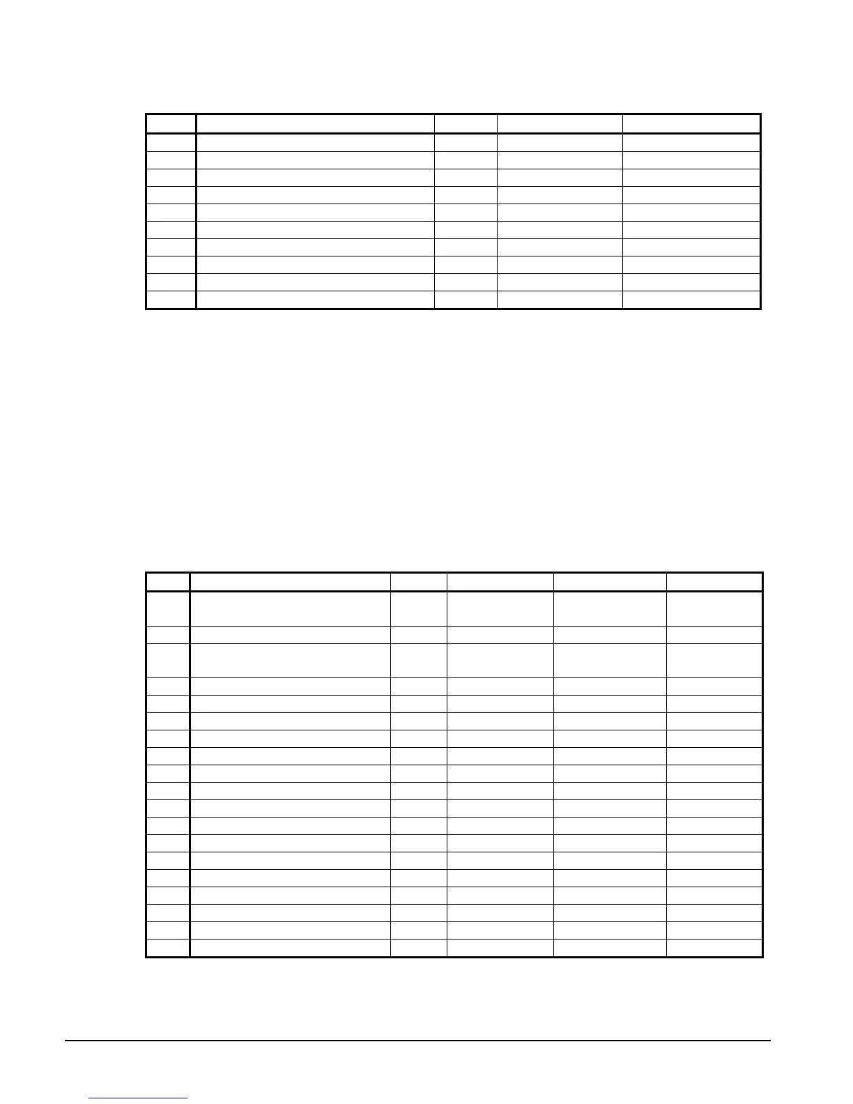
Table 11, Digital Inputs, Continued
# Description Type Signal Signal
9 Phase Voltage Fault #1 (See Note 1 Below) C1 0 VAC (Fault) 24 VAC (No Fault)
10 Phase Voltage Fault #2 (See Note 1 Below) C2 0 VAC (Fault) 24 VAC (No Fault)
11 Ground Fault Prot. #1 (See Note 2 Below) C1 0 VAC (Fault) 24 VAC (No Fault)
12 Ground Fault Prot. #2 (See Note 2 Below) C2 0 VAC (Fault) 24 VAC (No Fault)
13 Remote Start/Stop UT 0 VAC (Stop) 24 VAC (Start)
*14 Open
*15 Motor Protection #1 C1 0 VAC (Fault) 24 VAC (No Fault)
*16 Motor Protection #2 C2 0 VAC (Fault) 24 VAC (No Fault)
17 Ice Mode Switch UT 0 VAC (Normal) 24 VAC (Ice)
18 Heat Mode Switch UT 0 VAC (Normal) 24 VAC (Heat)
Notes:
1. See Safety Alarms Table for “Phase Voltage Protection”. Units with single point electrical
connection will have one PVM with Inputs 9 and 10 wired together. Units with multiple point
connection will have two PVM’s with Input 9 for Electrical Circuit #1 and Input 10 for
Electrical Circuit #2.
2. See Safety Alarms Table for “Ground Fault Protection”. Units with single point electrical
connection will have one GFP with Inputs 11 and 12 wired together. Units with multiple point
connection will have two GFP’s with Input 11 for Electrical Circuit #1 and Input 12 for
Electrical Circuit #2.
Table 12, Digital Outputs
The following parameters are digital outputs from this controller.
C1 = Refrigerant Circuit #1, C2 = Refrigerant Circuit #2, UT = Unit, & *n = Refrigerant Dependent
# Description Type Load Output OFF Output ON
1 Alarm
C1,C2,
UT
Alarm Indicator Alarm OFF Alarm ON
2 Evaporator Water Pump UT Pump Contactor Pump OFF Pump ON
3
Condenser Water Pump – Water
Cooled = Y
C1 / UT
Fan Contactor/
Pump Contactor
Fan OFF Fan ON
4 Motor Control Relay #1 = Compr#1 C1 Starter Compressor OFF Compressor ON
5 Motor Control Relay #3 = Compr#3 C1 Starter Compressor OFF Compressor ON
*6 Motor Control Relay #5 = Compr#5 C1 Starter Compressor OFF Compressor ON
7 Liquid Line #1 C1 Solenoid Cooling OFF Cooling ON
8 Tower Fan #1-Water Cooled=Y C2 /UT Fan Contactor Fan OFF Fan ON
9 Motor Control Relay #2 = Compr#2 C2 Starter Compressor OFF Compressor ON
10 Motor Control Relay #4 = Compr#4 C2 Starter Compressor OFF Compressor ON
*11 Motor Control Relay #6 = Compr#6 C2 Starter Compressor OFF Compressor ON
12 Liquid Line #2 C2 Solenoid Cooling OFF Cooling ON
13 Condenser Fan #3 C1 Fan Contactor Fan OFF Fan ON
14 Hot Gas Bypass #1 C1 Solenoid Cooling OFF Cooling ON
15 Hot Gas Bypass #2 C2 Solenoid Cooling OFF Cooling ON
*16 Condenser Fan #4 (R134a) C2 Fan Contactor Fan OFF Fan ON
*17 Condenser Fan #5&7 (R134a) C1 Fan Contactor Fan OFF Fan ON
18 Condenser Fan #8 C2 Fan Contactor Fan OFF Fan ON
18 Condenser Fan #6&8 C2 Fan Contactor Fan OFF Fan ON
 Loading...