OMM TGZ-1 TGZ 040A through TGZ 190A 25
Inputs and Outputs
The main controller used in the TGZ is either a Carel PCO2 or a PCO3. An expansion module is
also be required for additional outputs on some unit configurations. The software is designed for
use with R-410a water chillers as well as TGZ Templifier units. The selection of the type of
refrigerant (R-134a) is made at the factory and sets certain inputs and outputs.
Large PCO2/PCO3 Controller
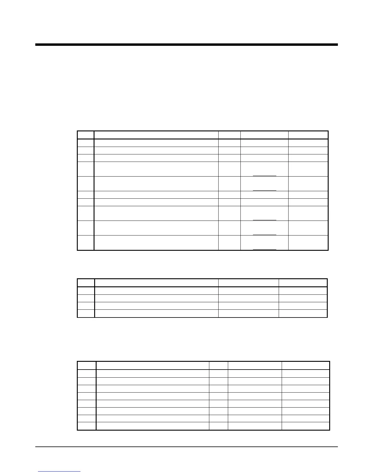
Table 9, Analog Inputs
The following parameters are analog inputs to this controller.
Type: C1 = Refrigerant Circuit #1, C2 = Refrigerant Circuit #2, UT = Unit
# Description Type Signal Source Range
*1 Evaporator Refrigerant Pressure #1 C1 0.1 to 0.9 VDC
0 to 132 psi
*2 Evaporator Refrigerant Pressure #2 C2 0.1 to 0.9 VDC
0 to 132 psi
*3 Condenser Refrigerant Pressure #1 C1 0.1 to 0.9 VDC
3.6 to 410 psi
4 Leaving Evaporator Water Temperature UT
NTC Thermister
(10k@25°C)
-58 to 212°F
5 Condenser Entering Water Temperature UT
NTC Thermister
(10k@25°C)
-58 to 212°F
*6 Condenser Refrigerant Pressure #2 C2 0.1 to 0.9 VDC
3.6 to 410 psi
7 Reset of Leaving Water Temperature UT 4-20 mA Current 0-(10 to 80°F)
*8 Condenser Leaving Water Temperature UT
NTC Thermister
(10k@25°C)
-58 to 212°F
9 Compressor Suction Temperature #1 C1
NTC Thermister
(10k@25°C)
-58 to 212°F
10 Compressor Suction Temperature #2 C2
NTC Thermister
(10k@25°C)
-58 to 212°F
Table 10, Analog Outputs
The following parameters are analog outputs from this controller.
# Description Output Signal Range
1 Cooling Tower Bypass Valve Position 0 to 10 VDC 0 to 100% Open
2 Cooling Tower VFD Speed 0 to 10 VDC 0 to 100%
3 Circuit #1 Electronic Expansion Valve 0 to 10 VDC 0 to 100%
4 Circuit #2 Electronic Expansion Valve 0 to 10 VDC 0 to 100%
Table 11, Digital Inputs
The following parameters are digital inputs to this controller.
C1 = Refrigerant Circuit #1, C2 = Refrigerant Circuit #2, UT = Unit, & *n = Refrigerant
Dependent
# Description Type Signal Signal
1 Unit OFF Switch UT 0 VAC (Stop) 24 VAC (Auto)
2 Pump Down Switch #1 C1 0 VAC (Stop) 24 VAC (Start)
3 Evaporator Water Flow Switch UT 0 VAC (No Flow) 24 VAC (Flow)
*4 Open
5 Open
6 Pump Down Switch #2 C2 0 VAC (Stop) 24 VAC (Start)
*7 Open
*8 Condenser Water Flow Switch UT 0 VAC (No Flow) 24 VAC (Flow)
Continued on next page.
 Loading...