K
Kenneth HickmanAug 20, 2025
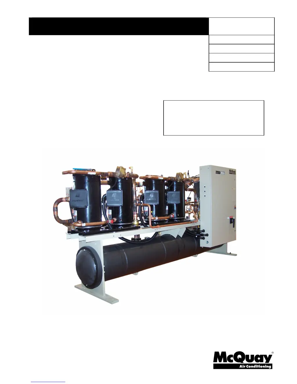
What to do if McQuay TGZ 040A Water Heater has high discharge pressure?
- CChristopher JonesAug 20, 2025
High discharge pressure in your McQuay Water Heater can stem from several issues: * Insufficient condenser water or water temperature being too high. Investigate ways to increase hot water supply or lower the temperature of the hot water and check the operation of the supplementary heater. * Fouled condenser tubes. Clean them. * Noncondensables in the system. Purge them. * The system might be overcharged with refrigerant. Remove the excess refrigerant. * The discharge shutoff valve could be partially closed. Open the valve fully. * The condenser may be undersized. Check the condenser rating tables against the operation.