Instruction Manual DSR digital regulator - rev. 05 - pag. 4
•
Precision of voltage regulation: ± 1% from no-load to nominal load in static condition, with any power
factor and for frequency variations ranging from -5% to +20% of the nominal value.
•
Transient power drops and overvoltage within ± 15%
•
Voltage recovery time within ± 3% of the value set, in less than 300 msec.
•
Transient overvoltage during start up: less than 5% of nominal voltage.
•
Single phase sensing
•
Parameters: VOLT, STAB, AMP and Hz can be set with trimmers (default) 50/60Hz through a
“jumper” (default); all parameters can be programmed via software.
•
Analogical remote control of output voltage is possible through external voltage (0÷2,5Vdc) or with a
10 Kohm linear potentiometer.
•
Environmental temperature: -25°C ÷ +70°C
•
Underspeed protection with adjustable threshold and slope
•
Overvoltage and undervoltage alarms
•
Excitation overcurrent protection with delayed intervention
•
Management of temporary short circuits (start up of asynchronous motors)
•
Open collector output (not insulated) signalling intervention of protective devices (insulation on optional
DI1 module) with programmable activation with respect to the individual alarms and the possibility to de-
lay intervention.
•
Abnormal operation conditions storage (type of alarm, number of events, duration of the last event, total
time)
•
Memorization of the regulator operation time (starting from revision 11 of the Firmware)
•
RS232 and RS485 serial communications interface (with optional DI1 module)
WARNING : Operation of the DSR is not specified below 12 Hz.
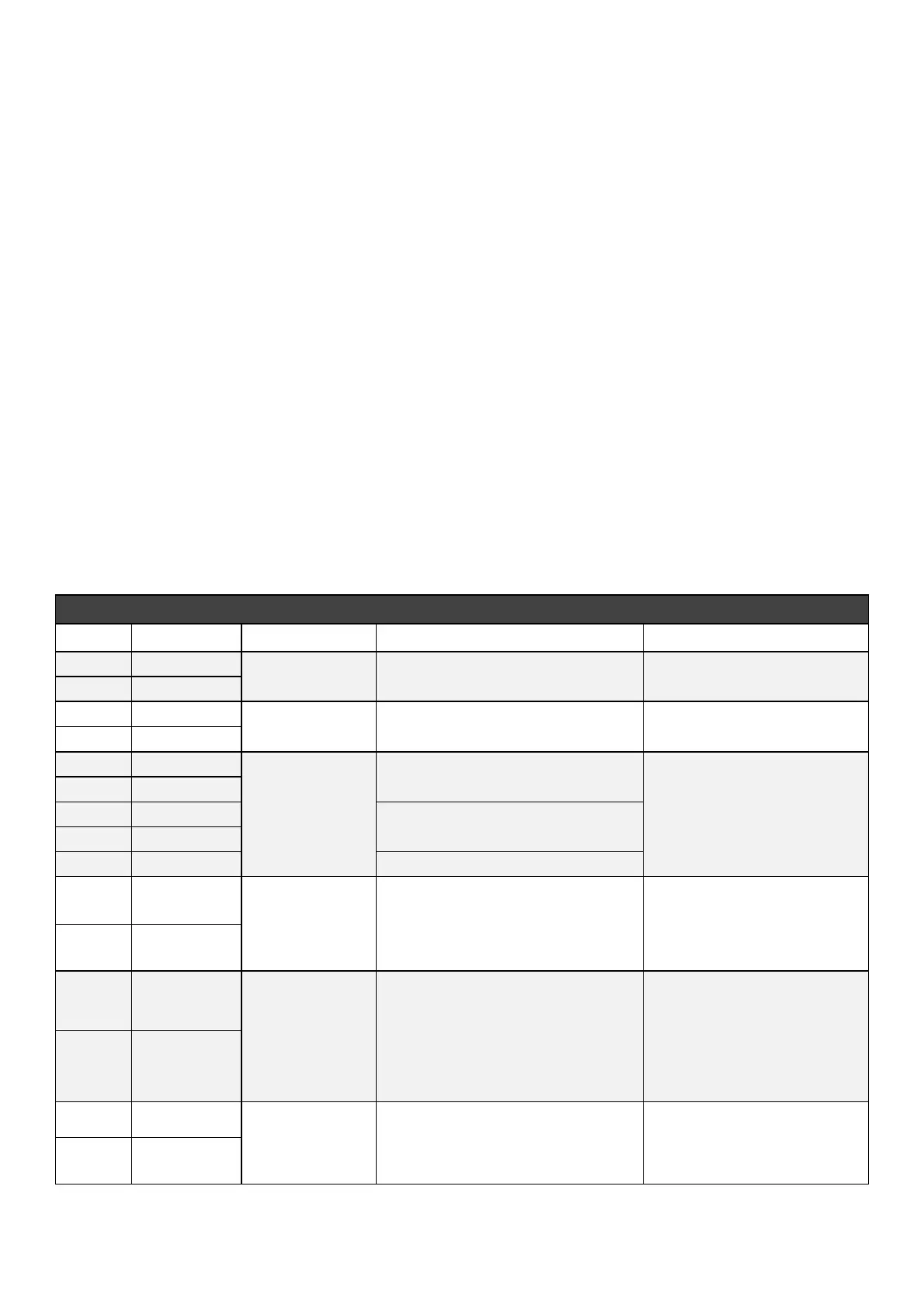
3. Inputs and Outputs: technical specifications
TABLE 1 : CONNECTOR CN1
Function Specifications Notes
1 Exc-
Excitation
Continuous Rating: 4Adc
Transitory Rating: 12Adc at peak
2 Aux/Exc+
3 Aux/Exc+
Power
Frequency: from 12Hz to 72Hz
Range: 40Vac - 270Vac
9 Aux/Neutral
4 F_phase
Range: 140Vac - 280Vac
Burden: <1VA
Measurement of average value
(rectified) or actual effective va
lue for voltage adjustment
5 F_Phase
6 H_phase
Range: 70Vac - 140Vac
Burden: <1VA
7 H_phase
8 Aux/Neutral
10 Vext/Pext
Input for remote
voltage control
Type: Not insulated
Range: 0 - 2,5 Vdc or 10K Potentiometer
Adjustment: from – 14% to + 14%
(3)
Burden: 0 - 2 mA (sink)
Max length: 30m
(2)
Tolerates voltages from - 5V to
+ 5V but for values exceeding
the range it is automatically
disabled
11 Common
12 50/60Hz
50/60 Hz
Jumper Input
Type: Not insulated
Max length: 3m
Selection of underspeed
protection threshold 50·(100%-
Hz%) or 60·(100%-Hz%)
Hz% is the position relative to
the Hz trimmer or the
percentage value of parameter
21
13 Common
14 A.P.O.
Active
protections output
Type: Non-insulated open collector
Current : 100mA
Voltage: 30V
Max length: 30m
(2)
Both activating alarm and
delay time are programmable
15 Common
Sensing
NOTE (1) The terminals are connected to each other on the board: 2 with 3, 4 with 5, 6 with 7, 8 with 9, 11 with 13 and 15.
NOTE (2) With external EMI filter SDR 128/K, see Fig.10 (3m without EMI filter)
NOTE (3) Starting from revision 10 of the Firmware. It is convenient do not exceed ±10%
 Loading...