34
TECHNICAL DATA
Rated output 2.5 kW
Nominal speed 3000 rpm
Displacement 139 cm³
Starter Cord start
Oil volume 0.40 l, SAE 10W-30
Fuel tank capacity 0.80 l
Rotating blades Ø 260 mm
Working width 360/590 mm
Sound pressure level, LpA 75.0 dB(A), K=3 dB
Sound power level, LwA* 90 dB(A), K=3 dB
Sound power level, LwA** 93 dB(A)
Vibration level
Left handle: 1.721 m/s², K=1.5 m/s²
Right handle: 1.592 m/s², K=1.5 m/s²
Weight 33 kg
*Measured, **Guaranteed
Always wear ear protection.
The declared values for vibration and noise, which
have been measured according to a standardised
test method, can be used to compare dierent
tools with each other and for a preliminary
assessment of exposure. The measurement
values have been determined in accordance with
EN ISO 3744:1995, ISO 11094:1991.
WARNING!
The actual vibration and noise level when
using tools may dier from the specied
maximum value, depending on how the
tool is used and the material. It is therefore
necessary to determine which safety
precautions are required to protect the user,
based on an estimate of exposure in actual
operating conditions (taking into account all
stages of the work cycle, e.g. the time when
the tool is switched o and when it is idling,
in addition to the start-up time).
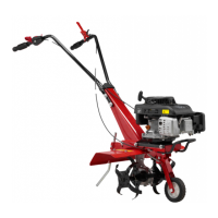
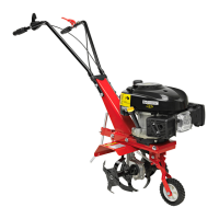
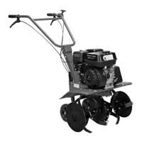
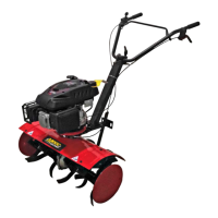
DESCRIPTION
1. Clutch handle
2. Starter handle
3. Carry handle
4. Rotating blades
5. Depth stop
6. Throttle lever
FIG. 1
ASSEMBLY
NOTE:
Switch o the engine and disconnect the
spark plug lead from the spark plug before
tting the blades.
FITTING THE HANDLE
FIG. 2
FITTING THE DEPTH STOP
FIG. 3
FITTING THE BLADES
1. Put the blades on the output shafts on
the gearbox.
FIG. 4
NOTE:
The blades must be tted on the correct side.
The left blade is marked L and the right is
marked R.
2. Align the holes in the blade fasteners with
the holes in the shafts and lock in place
with the cotters.
FIG. 5
3. Fit the covers in the holes in the blades to
prevent soil getting in.
FIG. 6