Caution:
!
The control unit can connect to one pump and one underwater light only (SSC-TLT
Series Only)
!
The current loading of the pumped connected must not exceed 8 Amp. (SSC-TLT
Series Only)
Electrolytic cell and Electrode
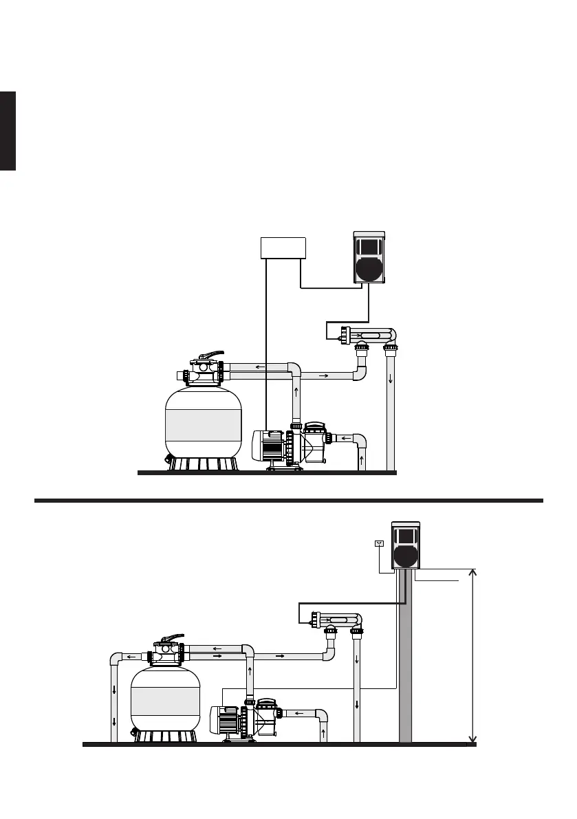
1. The cell must be installed horizontally
2. Connect the water inlet and outlet to the Cell Unit. The water flow direction
must be as indicated on the Cell.
3. To avoid lost of chlorine, the Cell should be installed at the end of the
filtration system, right before the pool water return.
Installation
SSC-E SERIES
SSC-T & SSC-TLTSERIES
6
Waste
Filter Pump
Suction
(Water from Pool)
Return to Pool
Pump
Return
Pump Cable
Cell Cable
Cell
Power
Supply
Control Box
Pool Light
Cable (if fitted)
1.5meter
Pole
Power Supply
Control Box
Pump Cable
Control Box
Cable
Cell Cable
Pump
Return
Filter Pump
Suction
(Water from Pool)
Return to Pool
Cell
English