10
2.7. Measurement ranges
The equipment has 4 resistance measurement ranges:
Range Unit Reading resolution
0 – 20.00 Ω 0,01
0 – 200.0 Ω 0,1
0 – 2000 Ω 1
0 – 20 kΩ 0,01
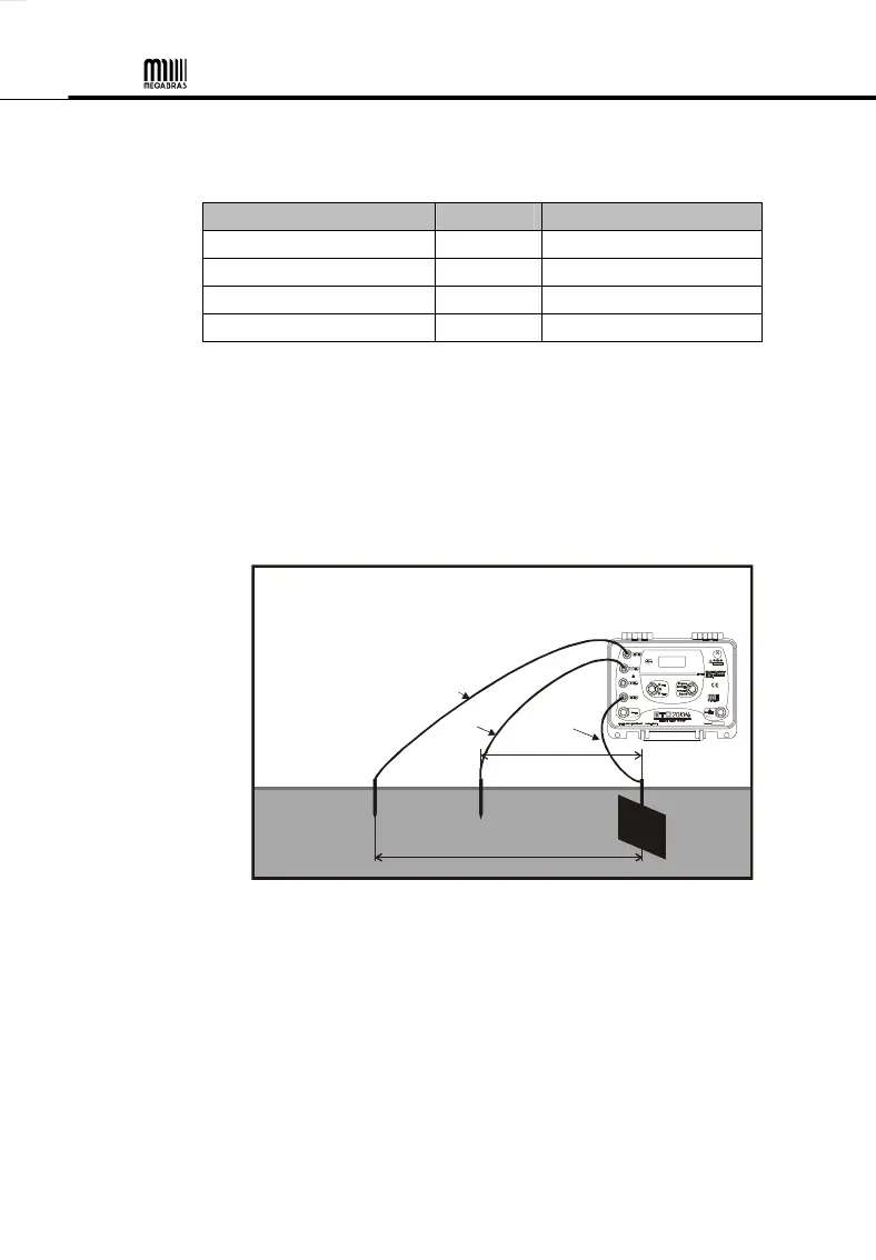
2.8. Grounding resistance measurement
1. Insert in the soil the two auxiliary rods: the E3 current rod and the E2
voltage rod. Connect them by means of provided cables to H(EC)#
and S(ET)$ output terminals, respectively. The E(EXC)& terminal must
be connected to the grounding system under test (E1) using the 5
meters cable (see fig. 01).
E3 E2
fig. 01
D2
40m cable
20m cable
5m cable
rod
rod
Ground
to be
2. Select the R(3 pole) position in the FUNCTION Selector Switch(.
Select the 20 kΩ range with the RANGE Selector Switch* and press
the START Pushbutton'. If the resistance value is lower than 2 kΩ,
select the most adequate, electing the scale from the highest to the
lower. If the acoustic alarm bips, this indicates some abnormality in the
rods wiring, the reason may be a misconnection or an excessively high
diffusion resistance in the current rod. Check the installation to fix this
problem. (See item 5).