www.megger.com DLRO®200
9
General description
3. General description
The Megger
®
DLRO
®
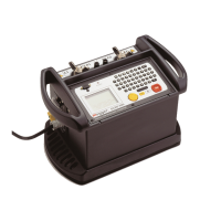
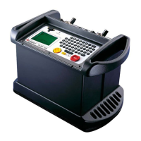
200 is an AC powered low resistance ohmmeter deigned to measure DC resistances in the
low milliohms or microhms using a maximum test current of 200 Amps DC The maximum test current available is
dependent upon the power supply, the resistance of the test leads and the resistance of the item being tested. Full
details are available in the SPECIFICATIONS section later in this book.
The power lead entry is located on the left-hand side panel and marked “100-265 V AC, 10 A max., 50/60Hz” for
the DLRO200, or ‘115 V AC 10 A max. 50/60Hz’ for the DLRO200-115. The main On/Off switch is located next to
the power lead entry. All other controls are mounted on the front panel. Should the supply earth be inadequate the
instrument will refuse to switch on, the display will remain blank. An additional earth terminal is provided on the left
ahd side of the instrument.
3.1 Principle of operation
The required current is set before the test starts. When the TEST button is pressed, after a short delay the current
increases to the set current, the voltage detected across the “P” leads is measured, and the current then reduces to
zero.
Operation is controlled using the two-axis paddle and the menu system, which appears on the backlit liquid crystal
display. The keyboard is used to set the desired test current and to add notes, which may be stored with test results in
on board memory for later download via the RS232 socket provided. The measured resistance, the actual test current
and measured voltage are clearly presented on the display after the test is complete.
The use of a four terminal measurement technique removes the test lead resistance from the measured value
although the use of lightweight current leads may prevent the DLRO200 from producing the full requested current.
In this case the instrument will produce the highest current possible taking into account the resistance of the current
leads and the item being tested.
Before a test may be started the potential test lead contact is monitored to ensure good contact is present.
This reduces the chance of erroneous readings and prevents arcing at the contact point, which would otherwise
damage the item under test and the test lead contacts. A resistance measurement takes approximately 10 seconds.
DLRO200 is supplied complete with a pair of 5 metre (16 feet) current leads terminated with large clamps, and
smaller, lighter potential leads. Other lengths and terminations are available if required.
The large terminals C1 and C2 supply a low voltage (from zero to 5 volts) which is adjusted automatically to produce
the desired current (from 10 A to 200 A). C1 is the positive terminal. This DC voltage is half wave rectified and
unsmoothed in the DLRO200, the inductance of the test leads providing sufficient smoothing for the current.
The DLRO200-115 has additional smoothing within the instrument.
P1 and P2 are voltage measuring terminals. P1 is nominally positive, but connections can be reversed without
affecting the measurement. All four terminals are floating.
A warning will be given if dangerous voltages are connected to any terminal (C or P) with respect to ground.


 To Next Page