www.megger.com t
21
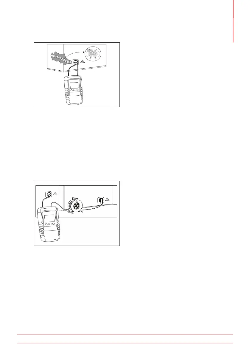
Operating Principle
Figure 16:
In order to prevent these effects the connection should be carried out as shown in figure 17. The return path
is supplied by a separate cable. The distance in voltage circuits will be up to 2.5 meters.
Make sure there is sufficient distance between the cable under test and the external lead to prevent
interference between the two.
WARNING : Care must be taken when making any connection to live or potentially live circuits.
Correct safety procedures must be followed.
NOTE : Switching sensitivity between Level 1 and Level 3 increases the sensitivity by a factor of 5.
Figure 17:
5.17 Identifying multiple installed conductors (double-pole method)
When identifying multiple installed conductors, each conductor must be isolated and not carrying any
voltage. One end of the lead will require shorting together (as shown in Figure 18) If multiple transmitters
are available, each transmitter should be set to a unique signal (1 - 7). Connect the transmitters as shown in
figure 18.

 Loading...