www.megger.com
t
22
Operating Principle
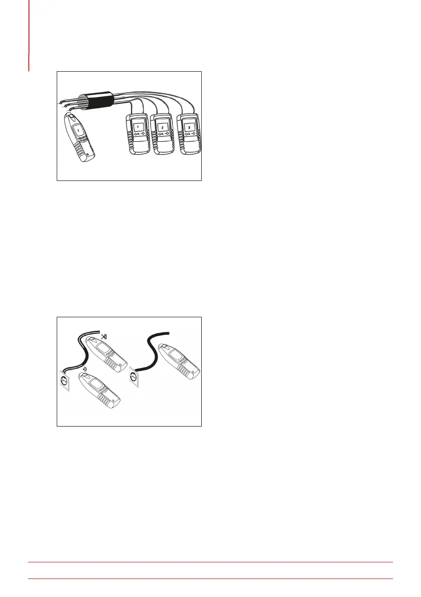
Figure 18:
NOTE : The stripped lead terminals must be twisted together to ensure a good electrical
connection, as shown in Figure 18.
If only one transmitter be available, each pair should be identified individually, one at a time.
NOTE : Switching sensitivity between Level 1 and Level 3 increases the sensitivity by a factor of 5.
5.18 Non-contact voltage detection
No transmitter is required for this application. (Figure 19)
Select non-contact voltage mode by pressing the NVC button on the receiver, NCV should appear on
the display.
Figure 19:
The display bargraph indicates the signal intensity of a detected voltage. An audible tone is produced that
changes in pitch as the proximity to the voltage is reduced.
WARNING : Although different signal intensities may indicate the presence and level of voltage, a
dedicated voltage measurement instrument MUST be used to prove voltage value if required.