resistance figures are available and lead length is
measured.
A reading of between 100 mΩ and 500 mΩ will be
indicated on the broken scale line together with the display
of . Refer to the appliance manufacturer.
Readings greater than 500 mΩ are indicated by t h e
flashing display of the word FAIL.
On the 10 Amp range, the flashing display of w i l l
appear for resistance greater than 600 mΩ, indicating that
the test current is below a satisfactory test level. It is
suggested that the 25 A m p range should then be used.
Insulation Te s t
Class I Appliance
1. Press and hold the Insulation Test switch. The
Insulation screen is displayed.
2. Insulation resistance value is displayed directly
in M .
3. Release the Test switch.
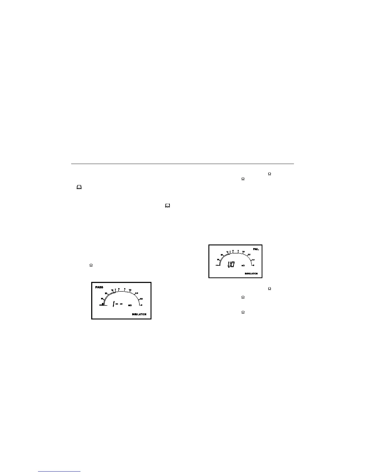
As a general rule, Class I appliances should have an
insulation resistance value greater than 1 M .
A reading of less than 0.25 M is indicated with the word
FAIL.
Class II Appliance
1. Connect the Earth Bond test lead (or probe if
available) to the 10A/25A terminal.
2. Press and hold the Insulation Test switch. The
Insulation screen is displayed.
3. Using the crocodile clip, probe areas of likely
leakage around the insulation areas. i.e. joins /
apertures / metal parts.
4. Release the Test switch.
5. Disconnect the Earth Bond test lead.
As a general rule, Class II appliances should have an
insulation resistance value greater than 2 M .
A reading of greater than 2 M is indicated on the solid
scale line together with the word PASS.
A reading of less than 0.25 M is indicated with the word
FAIL.
Appliance Testing
12
 Loading...