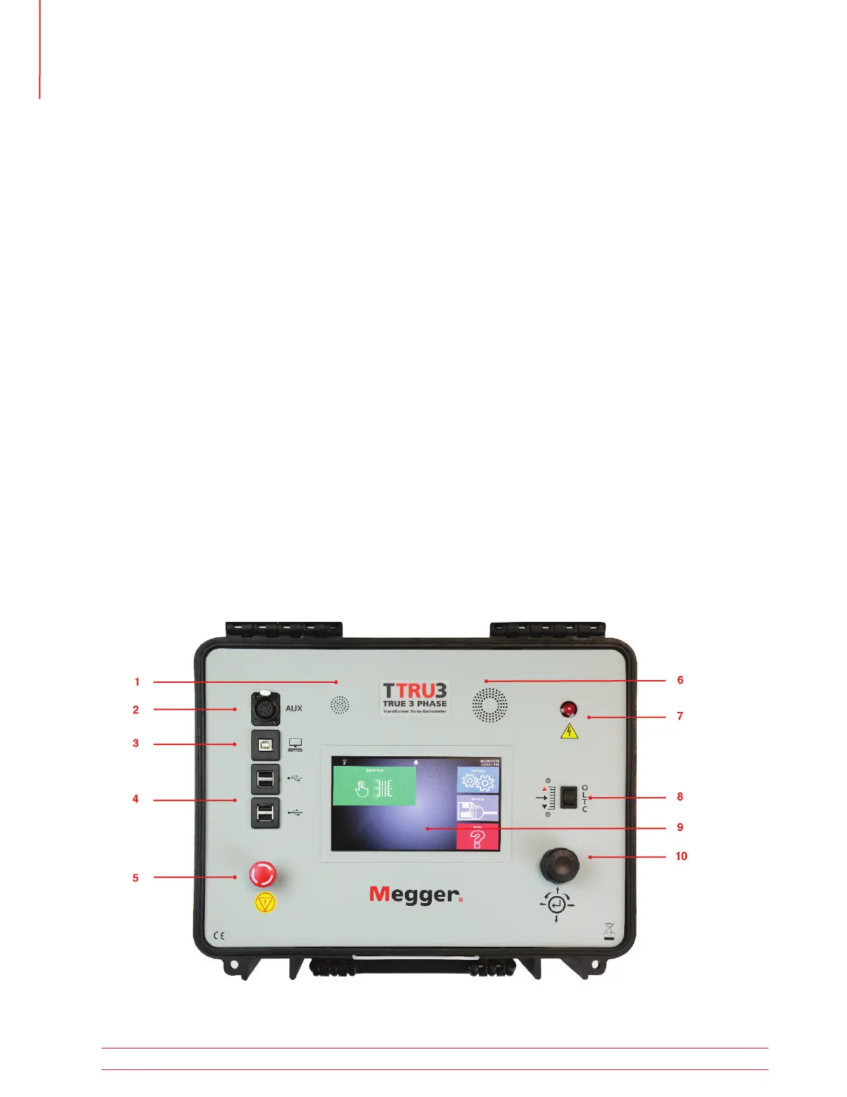
6. Fan
Automatically enabled when internal tempera-
ture exceeds factory limit.
7. Warning Indicator
Indicates when voltage is applied to test leads.
8. Manual OLTC Control Switch
Controls connected OLTC tap changer up/down.
Requires OLTC cable connected to transformer.
9. Touchscreen
Primary GUI control interface. Designed for out-
door (1100 NITS) and industrial environments.
10. Rotary and Directional Control Knob
Supplemental GUI control interface.
1.5 Top Panel
1. Speaker
Used for sounding countdown for test.
2. AUX Port
Used for connecting auxiliary equipment.
3. USB On the Go
TTRU3 appears as a thumb drive containing PC
SW, user manual, and data sheet.
Enables PC Control after PC SW Installed.
4. USB A
Print, export
5. Emergency Stop
Used to immediately interrupt voltage output.
Prevents tests from starting if engaged.
Rotate clockwise to disengage.
Introduction
8 TTRU3 User Manual us.megger.com