EasyManua.ls Logo

Megger TDR2050 - User Manual

Megger TDR2050
4 pages
Print Icon
To Next Page IconTo Next Page
Loading...
3. CONNECTION
For best performance ensure that the
test leads are not unduly separated
Only use Megger approved fused
test leads
Ensure that the test leads are in good
condition and working order
TDR2050 Quick Start Guide
2. SELECT TEST MODE
a.
Press to select
Hold
TDR2050
OK
Hold
TDR2050
OK
1. POWER UP
Press and hold to turn TDR on
Hold
TDR2050
OK
c.
Press OK key to select
b. Use cursor keys to select test mode
required - choose T1
Question and Answer IconNeed help?

Do you have a question about the Megger TDR2050 and is the answer not in the manual?

Summary

Power Up and Mode Selection

Power On Procedure

Press and hold the power button to turn the TDR unit on.

Choosing the Test Mode

Select the desired test mode using the device's cursor keys.

Connection Guidelines

Test Lead Best Practices

Ensure test leads are not separated and are in good working condition.

Parameter Configuration

Accessing Parameter Settings

Press the spanner/setting symbol to access the parameter menu.

Setting Velocity Factor

Configure the velocity factor based on cable manufacturer data or examples.

Setting Cable Impedance

Adjust cable impedance using the arrows; set to maximum if unknown.

Adjusting Signal Gain

Set gain level to best display the trace using the up/down arrows.

Setting Pulse Width

Adjust pulse width for optimal fault visibility based on fault distance.

Defining Cable Distance

Set the distance parameter to be greater than the known cable length.

Cursor Operations

Selecting and Swapping Cursors

Press C1-C2 buttons to select and swap between cursors for measurement.

Positioning Cursors

Use left/right arrows to move the selected cursor along the trace.

Placing Cursors on Trace

Move C1 to the end of test leads and C2 to the first significant reflection.

Performing Delta Measurements

TDR displays total distance to C2 and the difference between C1 and C2.

Typical Velocity Factors

Overview

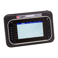
The Megger TDR2050 is a Time Domain Reflectometer designed for cable fault location and analysis. It is a portable, handheld device that allows users to quickly and accurately identify faults in various types of cables. The device features a clear display and intuitive controls, making it suitable for both experienced technicians and those new to TDR testing.

Function Description

The primary function of the TDR2050 is to locate faults in electrical cables. It operates by sending a pulse down the cable and measuring the reflections that return. The time it takes for a reflection to return, combined with the cable's velocity factor, allows the device to calculate the distance to the fault. The TDR2050 can identify various types of faults, including opens, shorts, and impedance mismatches. It supports different test modes, such as T1, T2, T1 & T2, T1-T2, T2-T1, T1-M, and T2-M, offering flexibility for different testing scenarios. The device displays a trace on its screen, visually representing the cable's impedance profile and highlighting the location of any discontinuities. Cursor measurements enable precise fault location and delta measurements provide the difference between two cursor positions, aiding in detailed analysis.

Usage Features

The TDR2050 is designed for ease of use, with a straightforward operational flow.

  1. Power Up: To begin, users simply press and hold the power button to turn the TDR on.

  2. Select Test Mode: After powering on, the device prompts the user to select a test mode. This is done by pressing the 'select' button and then using the cursor keys to navigate through the available options (e.g., T1, T2, T1 & T2). The chosen mode is then confirmed.

  3. Connection: For accurate measurements, it is crucial to connect the test leads correctly. The manual emphasizes ensuring that the test leads are not unduly separated and are in good condition. Only Megger-approved fused test leads should be used to maintain safety and performance.

  4. Select Parameters: Before testing, several parameters need to be configured to match the cable being analyzed.

    • Manual Mode: Users must ensure the device is in manual mode by pressing the spanner/setting symbol.
    • Velocity Factor (VF): The correct velocity factor, typically obtained from the cable manufacturer, must be set. If unknown, a table of typical velocity factors for common cable types (XLPE, PILC) is provided in the manual as a reference. The VF can be adjusted using the UP/DOWN arrows and confirmed with the 'OK' button. The TDR2050 allows setting the velocity factor between 0.2 and 0.99.
    • Cable Impedance: If the cable impedance is unknown, it should be set to the maximum value using the arrows and confirmed. The device offers five output impedances (25, 50, 75, 100, 140 ohms) and an auto impedance matching feature.
    • Gain: The gain level needs to be adjusted to provide the clearest trace on the display. This is done by toggling the gain using the trace arrows and confirming the setting.
    • Output Pulse Width: The output pulse width can be set at a mid-point and then adjusted up or down until the fault becomes clear. A low pulse width is recommended for near-end faults, while a high pulse width is better for distant faults and concentric cables.
    • Cable Distance: The cable distance parameter should be adjusted to a value greater than the known length of the cable being tested.
  5. Moving Cursor: Once parameters are set and a trace is displayed, the cursors are used to pinpoint fault locations.

    • Cursor Selection: Cursors are selected by pressing the 'OK' key.
    • Cursor Choice: The device allows selection between C1 and C2.
    • Swap Cursors: The C1-C2 buttons are used to swap between the cursors, allowing the user to move either C1 or C2 independently.
    • Move Cursor: The left/right arrows are used to move the selected cursor along the trace.
    • Cursor Position on Trace: Typically, cursor C1 is moved to the end of the test leads (approximately 1.5 m), and cursor C2 is moved to the end of the cable or the first significant reflection, indicating a fault.
    • Delta Measurement: The TDR2050 provides a delta measurement, showing the total distance to cursor C2 and the difference in distance between C1 and C2, which is crucial for precise fault location.

Maintenance Features

While the manual does not explicitly detail a dedicated "maintenance" section, it implicitly highlights several aspects that contribute to the device's longevity and reliable operation:

  • Approved Test Leads: The emphasis on using "Megger approved fused test leads" and ensuring they are in "good condition and working order" is a key maintenance recommendation. This prevents damage to the device and ensures accurate readings.
  • Cable Parameter Accuracy: The importance of setting correct velocity factors and impedances, ideally from cable manufacturers, ensures the device operates within its optimal parameters, leading to accurate results and preventing misinterpretation of data. The provision of typical velocity factors serves as a guide for situations where manufacturer data is unavailable, indirectly supporting proper device usage and data integrity.
  • Trace Clarity: The instructions for adjusting gain and output pulse width to achieve a clear fault indication are also a form of operational maintenance, ensuring the device is used effectively to produce reliable diagnostic information.
  • Manufacturing Quality: The statement "This instrument is manufactured in the United Kingdom" and "The company reserves the right to change the specification or design without prior notice" implies a commitment to quality and continuous improvement, suggesting a robust and well-engineered device.

In summary, the Megger TDR2050 is a user-friendly and effective tool for cable fault location, designed with clear operational steps and an emphasis on accurate parameter configuration for reliable performance.

Megger TDR2050 Specifications

General IconGeneral
TypeTime Domain Reflectometer (TDR)
Battery LifeUp to 12 hours
IP RatingIP54
Pulse Width10 ns to 1 μs
Operating Temperature-10°C to +50°C
Storage Temperature-20°C to +60°C
InterfaceUSB
DisplayColor LCD
Velocity Factor0.3 to 0.99

Related product manuals