Do you have a question about the Megger torkel 820 and is the answer not in the manual?
Explains the manual covers TORKEL units and TXL Extra Loads, and applies to all models unless specified.
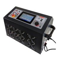
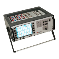
Describes TORKEL units as instruments for capacity tests, detailing programmable modes and key functions.
Explains TXL units are resistive loads used with TORKEL to increase loading capability, providing voltage ratings.
Describes TORKEL Win software for PC, visualizing voltage curves, controlling TORKEL, and generating reports.
Lists and explains warning symbols used on the instrument for caution, electric shock, heat, and WEEE.
Provides critical warnings about lethal voltage/current, isolation, cable handling, touching parts, and explosion risks.
Covers the Main Menu, Results, Test Battery, Language, and Basic Settings options.
Details Auto-limits for automatic voltage settings and Memory for saving test configurations.
Explains how to select the desired test method such as constant current, power, resistance, or profile.
Details the display and keys on the control panel for operation and parameter adjustment.
Explains the meaning of the OPERATING, Vmin, lot (Ah), and Time (h) status LEDs.
Describes the input used for measuring current externally via clamp-on ammeter or shunt.
Explains the F1 circuit breaker and details ALARM, START/STOP, and TXL output ports.
Describes the mains connector, ON/OFF switch, and battery connection terminals including VOLTAGE SENSE.
Focuses on performing tests using constant current, including safety precautions and preparation.
Lists essential safety measures for connecting/disconnecting cables, hazardous environments, and overheating.
Outlines initial steps: connecting to mains, switching on TORKEL, and connecting the battery cables.
Explains how to set the desired current and warning/stop limits for voltage, capacity, and time.
Details the procedures to start, pause, and properly end a discharge test using the control panel.
Explains how to conduct discharge tests at constant power, similar to constant current.
Details how to perform tests using a constant resistance load setting.
Provides steps to configure TORKEL for constant power or resistance testing.
Introduces profile testing, allowing current or power profiles with up to 19 time intervals and preparation steps.
Details setting up profile intervals, duration, and load values for the test execution.
Refers to the general procedure for starting a test after profile configuration.
Explains how external current measurement works using a DC clamp-on ammeter or shunt, and its applications.
Provides step-by-step instructions for configuring TORKEL for external current measurement via the menu.
Gives notes and steps for setting up and using a DC clamp-on ammeter with TORKEL.
Details how to connect the clamp-on ammeter and addresses potential errors and their solutions.
Explains the alarm function, buzzer, relay, connector, and lists events that trigger an alarm.
Describes how to reset the alarm by pressing any key.
Explains how the auto-limits function automatically calculates and sets voltage, capacity, and time limits.
Details the steps to activate and configure auto-limits for voltage, capacity, and time settings.
States TORKEL can connect to PC via TORKEL Win or TMC95 programs, detailing Win's capabilities.
Lists key features like voltage curve display, tabular data, and commands that can be issued to TORKEL.
Covers software package contents and PC requirements for installing TORKEL Win.
Guides on connecting TORKEL to PC, establishing communication, and loading the software key.
Details changing TORKEL language, performing tests using TORKEL Win, and viewing results.
Introduces the START/STOP connector for external control and explains its isolation and usage.
Details how to start and stop TORKEL discharge using a dry contact on the START/STOP connector.
Emphasizes making calculations to ensure TORKEL can provide and sustain the desired load current.
Presents tables detailing TORKEL's current limitation (Imax) and internal resistance for different voltage ranges.
Explains Imax, power limits, and how final voltage affects current due to internal resistance, with calculation methods.
Provides examples of load capacities for TORKEL models with different battery configurations.
Covers situations where a single TORKEL is insufficient and suggests using TXL Extra Loads or multiple TORKELs.
Explains TXLs are resistive loads regulated by TORKEL and lists checks required when connecting them.
Provides a guide for calculating the number of TORKEL and TXL units required for a system configuration.
Lists specifications for TXL models and presents example system configurations of TORKEL and TXL units.
Explains how current measurement works in a multi-unit system and which unit controls others.
Covers system setup, applying ammeters, and the critical sequence for starting multiple TORKEL units.
Identifies and describes TXL components: selector switch, circuit breaker, terminals, control ports, and mains.
Guides on setting the range selector switch, connecting TXL units, and performing tests.
Lists various cable sets for TORKEL/TXL connection and available clamp-on DC ammeters.
Mentions TORKEL Win software and lists other accessories like transport case and data loggers.
Addresses issues like a dark display or inability to switch on the circuit breaker F1.
Covers incorrect voltage readings and problems when TXLs are connected to TORKEL.
Addresses specific error messages on the display and provides solutions.
Details specific error messages like 'Error: Connection', 'Unable to regulate', and 'Error: External I' with solutions.
Outlines the four main calibration steps and provides general safety warnings for the procedure.
Details the specific procedure for calibrating the zero levels of TORKEL inputs.
Explains the steps required to calibrate the internal current measurement circuit.
Describes the process for calibrating both internal and external voltage measurements at two points.
Details the procedure for calibrating the external current measurement circuit at two points.
Explains the purposes of resetting TORKEL (default calibration, error recovery) and the procedure to perform it.
Lists detailed specifications for the TORKEL 820 model, including environment, dimensions, and technical parameters.
Lists detailed specifications for TORKEL 840/860 models, covering environment, dimensions, and technical parameters.
Provides specifications for TXL 830, 850, and 870 models, including voltage, current, power, and resistance.
| Brand | Megger |
|---|---|
| Model | torkel 820 |
| Category | Measuring Instruments |
| Language | English |