Do you have a question about the Megger 210600 and is the answer not in the manual?
Key warnings and precautions to be read and understood before and during instrument use.
Explains the meaning of warning symbols displayed on the instrument.
How the live circuit warning works and how to perform voltage measurements.
Step-by-step guide for performing low resistance measurements.
Step-by-step guide for performing insulation tests, including discharge.
Details on insulation ranges, test voltages, accuracy, and environmental factors.
Details on low resistance measuring range, open circuit voltage, and accuracy.
Overload rating, operating/storage temperature and humidity limits.
Details on power supply, battery life, low battery indicator, and fuse types/replacement.
Instrument weight, dimensions, and cleaning instructions.
Lists included and optional accessories like carrying cases and fuses.
Information on instrument warranty, service, and contact details.
| Brand | Megger |
|---|---|
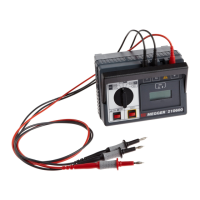
| Model | 210600 |
| Category | Measuring Instruments |
| Language | English |